
Transformer fireproof inspection detection device with global monitoring function

A detection device and transformer technology, applied in the direction of measuring devices, measuring instrument components, instruments, etc., can solve the problems of detection blind spots, failure to achieve overall monitoring, and inability to find hidden dangers at the first time, so as to ensure safe and stable operation and detection Comprehensive and accurate, early detection effect

Pending Publication Date: 2022-02-08
STATE GRID HENAN ELECTRIC POWER ELECTRIC POWER SCI RES INST +3
View PDF0 Cites 0 Cited by
  • Summary
  • Abstract
  • Description
  • Claims
  • Application Information

AI Technical Summary

Problems solved by technology

[0003] When there is a fire hazard in the substation, some indicators inside the transformer will change, such as the temperature and humidity inside the transformer, the smoke concentration inside the transformer, the concentration of hydrocarbons, and the image inside the transformer will all change, so it can be used in A sensor is placed inside the power transformer to detect the real-time data of the transformer as a basis for judging whether there is an abnormality or a fire hazard in the voltage transformer. However, in the existing technology, the installation position of the sensor is relatively fixed, and only a single point of local detection can be achieved. There are detection blind spots. It is impossible to detect hidden dangers in the first place, and it is impossible to achieve overall monitoring, which affects the timeliness and effectiveness of transformer monitoring

Method used


Image

  • Transformer fireproof inspection detection device with global monitoring function
  • Transformer fireproof inspection detection device with global monitoring function
  • Transformer fireproof inspection detection device with global monitoring function

Examples


Embodiment Construction

[0018] In order to facilitate the understanding of the present invention, the present invention will be described more fully below with reference to the associated drawings. Preferred embodiments of the invention are shown in the accompanying drawings. However, the present invention may be embodied in many different forms and is not limited to the embodiments described herein. On the contrary, the purpose of providing these embodiments is to make the disclosure of the present invention more thorough and comprehensive.

[0019] In addition, an element in the present invention is said to be "fixed" or "disposed on" another element, and it may be directly on another element or an intervening element may also exist. When an element is referred to as being "connected to" another element, it can be directly connected to the other element or intervening elements may also be present. The terms "vertical," "horizontal," "left," "right," and similar expressions are used herein for pur...


PUM


Abstract

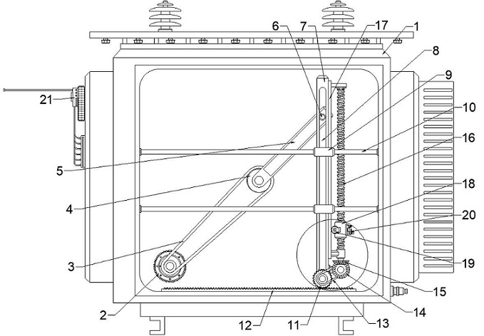
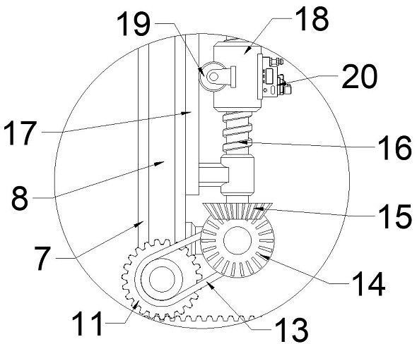
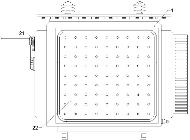
The invention discloses a transformer fireproof inspection detection device with a global monitoring function. The device comprises a motor installed on the rear wall of a transformer, a rotating mechanism connected with the output end of the motor, a sensor assembly movably arranged on the rear wall of the transformer, a reciprocating mechanism connected with the rotating mechanism and used for driving the sensor assembly to transversely move in the transformer, and a driven mechanism connected with the reciprocating mechanism and used for driving the sensor assembly to longitudinally move on the reciprocating mechanism. According to the fireproof inspection detection device, the rotating mechanism does circular motion to drive the reciprocating mechanism to drive the sensor assembly to transversely move close to the rear wall in the transformer, and meanwhile, the reciprocating mechanism drives the driven mechanism to drive the sensor assembly to longitudinally move on the reciprocating mechanism, so that global detection of the internal space of the transformer is realized, and the detection range is widened; and compared with the existing fixed single-point detection, the fire hazard can be found in advance, and precious time is gained for fire hazard treatment.

Description

technical field [0001] The invention belongs to the technical field of electric power inspection, and in particular relates to a transformer fire prevention inspection and detection device for overall monitoring. Background technique [0002] As an important device in the power system, the transformer plays a vital role in the transmission-transformation-distribution of the power system. In recent years, with the leap-forward development of my country's power grid construction, transformers have gradually developed towards large capacity, high current and high voltage levels. Transformer fire accidents occasionally occur, and show an upward trend year by year. Once a fire accident occurs in a transformer, it will burn down equipment, causing economic and property losses, and seriously threatening the safe and stable operation of regional and even inter-regional power grids. At the same time, the transformer is generally filled with dozens or hundreds of tons of insulating oi...

Claims


Application Information

Patent Timeline
IPC IPC(8): G01D21/02G01D11/00
CPCG01D21/02G01D11/00
Inventor 詹振宇王雷张劲光王栋楚明月姚浩伟张洋魏晓鸽王震宇宋怀涛秦恒洁王伟吴西博董大磊其他发明人请求不公开姓名
Owner STATE GRID HENAN ELECTRIC POWER ELECTRIC POWER SCI RES INST
Learn More