Method and system for measuring IQ two-path delay inequality and frequency response of transmitter

A frequency response and measurement method technology, applied in the field of communication, can solve problems such as poor stability, high measurement cost, and complex implementation, and achieve the effects of improving feasibility, broadening application scenarios, and reducing computational complexity

Active Publication Date: 2022-02-08
HUAZHONG UNIV OF SCI & TECH
View PDF9 Cites 0 Cited by
  • Summary
  • Abstract
  • Description
  • Claims
  • Application Information

AI Technical Summary

Problems solved by technology

[0005] Aiming at the defects of the related technology, the object of the present invention is to provide a method and system for measuring the delay difference and frequency response of the transmitter IQ two-way, aiming at solving the problems of high measurement cost, poor stability and complex implementation in the prior art

Method used


Image

  • Method and system for measuring IQ two-path delay inequality and frequency response of transmitter
  • Method and system for measuring IQ two-path delay inequality and frequency response of transmitter
  • Method and system for measuring IQ two-path delay inequality and frequency response of transmitter

Examples


Embodiment Construction

[0062] In order to make the object, technical solution and advantages of the present invention clearer, the present invention will be further described in detail below in conjunction with the accompanying drawings and embodiments. It should be understood that the specific embodiments described here are only used to explain the present invention, not to limit the present invention. In addition, the technical features involved in the various embodiments of the present invention described below can be combined with each other as long as they do not constitute a conflict with each other.

[0063] The content involved in the above embodiment will be described below in conjunction with a preferred embodiment.

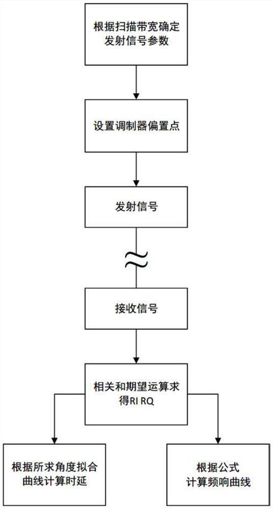
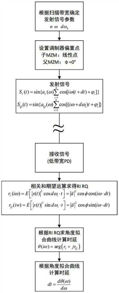
[0064] The embodiment of the present invention provides a method for measuring the time delay difference and frequency response of two IQ channels of a transmitter, including:

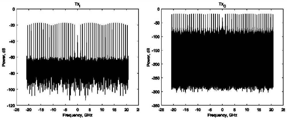
[0065] 1. Design two multi-tone signals with a specific relationship at the transmitter, includin...


PUM


Abstract

The invention discloses a method and a system for measuring IQ two-path delay inequality and frequency response of a transmitter, and belongs to the field of communication. According to the method, two signals meeting a specific relation are used at a transmitting end, a low-bandwidth photoelectric detector (PD) is used at a receiving end to receive the signals, low-frequency signals containing time delay information are extracted by utilizing the characteristic of low bandwidth, and the frequency response of a transmitter and IQ two-path time delay difference are measured at low cost. Moreover, the receiving end only needs to perform simple correlation and expectation operation on the signal by using the single-tone signal with the known frequency, and does not need to adopt a complex DSP (Digital Signal Processor) equalization algorithm to solve the time delay of the transmitting end, so that the signal processing complexity of the receiving end is reduced.

Description

technical field [0001] The invention belongs to the communication field, and more specifically relates to a method and system for measuring the time delay difference and frequency response of two IQ channels of a transmitter. Background technique [0002] In order to support the rapid growth of traffic in modern optical communication systems, higher order modulation formats and higher symbol rates are being gradually deployed. But as the modulation order and symbol rate increase, optical coherent systems become more sensitive to transceiver imperfections. One of the factors that obviously affects the high-speed transmission system is the delay difference between the in-phase / quadrature (IQ) branches of the transmitter, in addition to the bandwidth limitation of the system using electronic devices such as arbitrary waveform generators, photodetectors, etc. and other undesirable factors. [0003] So far, there have been methods to deal with impairments, including transmittin...

Claims


Application Information

Patent Timeline
Patent Type & Authority Applications(China)
IPC IPC(8): G01R23/02G01R23/16
CPCG01R23/02G01R23/16
Inventor 邓磊杨宇李洪雨程孟凡杨奇刘德明
Owner HUAZHONG UNIV OF SCI & TECH
Why Eureka
Try Eureka