
Ultrasonic imaging method and device and computer readable storage medium

An ultrasonic imaging method and computer technology, which are applied in ultrasonic/sonic/infrasound image/data processing, ultrasonic/sonic/infrasonic equipment control, ultrasonic/sonic/infrasonic diagnosis, etc. Problems such as low signal-to-noise ratio and limited frame rate optimization can improve imaging efficiency, improve image quality, and facilitate echo signal composite or image composite processing.

Active Publication Date: 2022-02-11
WUHAN UNITED IMAGING HEALTHCARE CO LTD
View PDF7 Cites 0 Cited by
  • Summary
  • Abstract
  • Description
  • Claims
  • Application Information

AI Technical Summary

Problems solved by technology

Classified by beam type, ultrasonic beam types generally include focused waves and non-focused waves (such as plane waves, divergent waves, wide beams, etc.), and different beam types have their own advantages and disadvantages. For example, focused waves have high focusing energy, but using focused There are many times when the wave is used for imaging; unfocused waves such as divergent waves and plane waves are suitable for higher frame rates but the focusing energy is inferior to that of focused waves. The imaging speed is fast and the sound field is relatively uniform but the image signal-to-noise ratio is low.
[0003]In the past ultrasonic imaging technology, focused waves were mostly used to emit concentrated waves in a certain area in order to improve the image quality of this area. However, although the traditional focused wave emission method has high energy, However, there are often cases where the frame rate optimization is limited due to the number of launches and the long launch time. At present, there are also cases where plane waves are used to supplement local launches in non-core areas (that is, areas outside the above-mentioned focused launch areas), but still Failure to fully integrate the respective advantages and disadvantages of different beam types, through reasonable planning and combination, in order to give full play to the respective advantages of multiple ultrasonic waves, improve the overall imaging efficiency, and better meet the imaging needs of users

Method used


Image

  • Ultrasonic imaging method and device and computer readable storage medium
  • Ultrasonic imaging method and device and computer readable storage medium
  • Ultrasonic imaging method and device and computer readable storage medium

Examples


Embodiment Construction

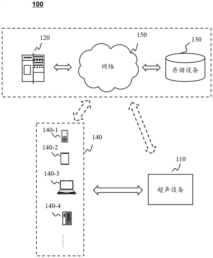
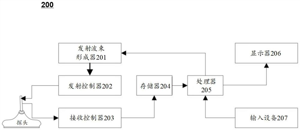
[0022] In order to more clearly illustrate the technical solutions of the embodiments of the present specification, the following briefly introduces the drawings that need to be used in the description of the embodiments. Apparently, the accompanying drawings in the following description are only some examples or embodiments of this specification, and those skilled in the art can also apply this specification to other similar scenarios. Unless otherwise apparent from context or otherwise indicated, like reference numerals in the figures represent like structures or operations.

[0023] It should be understood that "system", "device", "unit" and / or "module" as used herein is a method for distinguishing different components, elements, components, parts or assemblies of different levels. However, the words may be replaced by other expressions if other words can achieve the same purpose.

[0024] As indicated in the specification and claims, the words "a", "an", "an" and / or "the...


PUM


Abstract

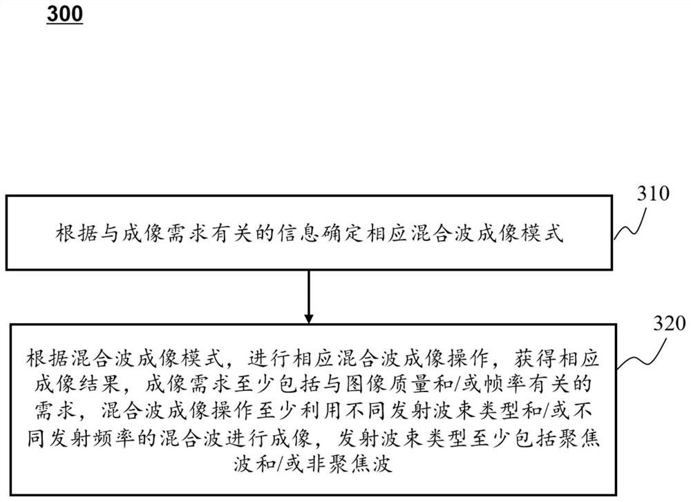
The embodiment of the invention discloses an ultrasonic imaging method and device and a computer readable storage medium. The method comprises the following steps: determining a corresponding mixed wave imaging mode according to information related to imaging requirements; and according to the mixed wave imaging mode, carrying out corresponding mixed wave imaging operation to obtain a corresponding imaging result; wherein the imaging requirements at least comprise requirements related to image quality and / or frame rate, the mixed wave imaging operation at least utilizes mixed waves of different transmitting beam types and / or different transmitting frequencies for imaging, and the transmitting beam types at least comprise focused waves and / or non-focused waves.

Description

technical field [0001] This specification relates to the technical field of ultrasonic detection and diagnosis, in particular to an ultrasonic imaging method, device and computer-readable storage medium. Background technique [0002] Ultrasonic imaging is to transmit ultrasonic waves from an ultrasonic probe to an object to be inspected, and generate an ultrasonic image according to echo signals of the ultrasonic waves. Classified by beam type, ultrasonic beam types generally include focused waves and non-focused waves (such as plane waves, divergent waves, wide beams, etc.), and different beam types have their own advantages and disadvantages. For example, focused waves have high focusing energy, but using focused Waves are emitted more times during imaging; non-focused waves such as divergent waves and plane waves are suitable for higher frame rates but the focus energy is inferior to focused waves. The imaging speed is fast, the sound field is more uniform, but the image ...

Claims


Application Information

Patent Timeline
Patent Type & Authority Applications(China)
IPC IPC(8): A61B8/00
CPCA61B8/48A61B8/52A61B8/54
Inventor 凌浩田志鑫
Owner WUHAN UNITED IMAGING HEALTHCARE CO LTD
Learn More