
SDPF system and calibration method thereof

A system calibration and DPF technology, applied in exhaust treatment, mechanical equipment, engine components, etc., can solve problems such as high hardware requirements, extremely difficult vehicle calibration, discounts, etc.

Active Publication Date: 2022-02-11
JAINGXI ISUZU AUTOMOBILE CO LTD
View PDF8 Cites 3 Cited by
  • Summary
  • Abstract
  • Description
  • Claims
  • Application Information

AI Technical Summary

Problems solved by technology

LNT is sensitive to sulfur and easily produces sulfate, so it will perform desulfurization (DeSOx) operation. The engine exhaust temperature needs to be controlled during the desulfurization stage. Generally, it will exceed 800°C and last for 10 minutes. The heat load assessment of the engine body is relatively large, and the hardware requirements are high. If the control is not good, the LNT will quickly deteriorate and the durability will be greatly reduced. Therefore, it is extremely difficult to calibrate the LNT route. The process will experience high temperature, and the hardware level of domestic conventional diesel engines cannot be popularized and applied. For this reason, the engine hardware costs of manufacturers who choose the LNT route will also increase

Method used


Image

  • SDPF system and calibration method thereof
  • SDPF system and calibration method thereof
  • SDPF system and calibration method thereof

Examples


Embodiment Construction

[0057] In the description of the present invention, it should be noted that the terms "center", "upper", "lower", "left", "right", "vertical", "horizontal", "inner", "outer" etc. The indicated orientation or positional relationship is based on the orientation or positional relationship shown in the drawings, and is only for the convenience of describing the present invention and simplifying the description, rather than indicating or implying that the referred device or element must have a specific orientation, or in a specific orientation. construction and operation, therefore, should not be construed as limiting the invention. In addition, the terms "first", "second", and "third" are used for descriptive purposes only, and should not be construed as indicating or implying relative importance.

[0058] In the description of the present invention, it should be noted that unless otherwise specified and limited, the terms "installation", "connection" and "connection" should be un...


PUM


Abstract

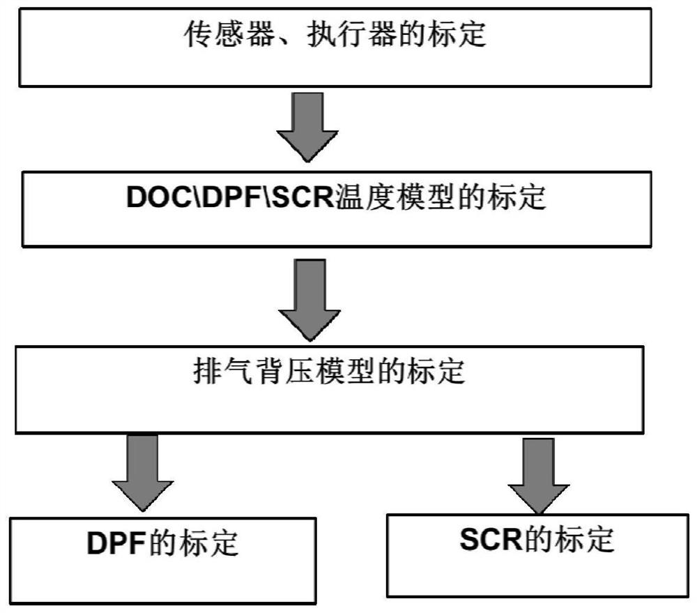
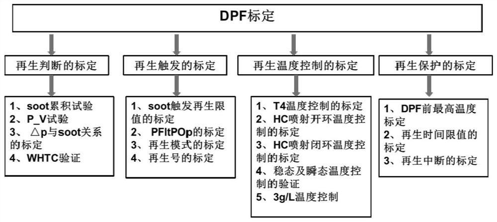
The present invention relates to an SDPF system, comprising: an exhaust gas purifier for oxidizing tail gas; a particle trap used for heating the tail gas; and a urea reduction converter used for carrying out supplementary treatment on the NOx tail gas which is not completely treated, wherein a carrier of the particle trap is coated with a copper-based molecular sieve, the particle trap is connected between the exhaust gas purifier and the urea reduction converter, the particle trap is further provided with a urea injection port, and the urea injection port is connected with the urea pump. The invention further provides a calibration method of the SDPF system. The calibration method comprises the following steps: calibrating the sensor and the actuator; calibrating DOC, DPF and SCR temperature models; calibrating an exhaust back pressure model; calibrating a DPF; and calibrating an SCR, wherein the calibration of the DPF comprises the calibration of regeneration judgment; calibration of regeneration triggering; calibration of regeneration temperature control; and calibration of regeneration protection; and the calibration of the SCR comprises the following steps of: calibrating the original emission of NOx; calibrating an SCR efficiency model; calibrating SCR ammonia storage; and calibrating the SCR during regeneration.

Description

technical field [0001] The invention relates to the technical field of automobiles, in particular to an SDPF system and a calibration method thereof. Background technique [0002] With the gradual tightening of China's emission regulations, light-duty diesel vehicles have begun to add DPF devices (particulate traps) in the stage of National V regulations to filter carbon particles emitted by the engine and limit PM (particulate matter mass) and PN (particulate matter number) ) tail pipe discharge. With the implementation of the National VI emissions, the post-processing technology route has undergone major changes, and the mainstream is the LNT route. The LNT route is divided into two stages in principle, ① capture stage: (1-2min) lean state (more oxygen), under the catalysis of Pt, NO and O 2 NO 2 , and adsorbed on the surface of the catalyst in the form of nitrate; ②Reduction stage: (2-5s) under rich combustion conditions, HC and CO decompose nitrate to release NO x , ...

Claims


Application Information

Patent Timeline
Patent Type & Authority Applications(China)
IPC IPC(8): F01N3/035F01N3/20F01N9/00F01N11/00
CPCF01N3/035F01N3/2066F01N3/208F01N3/2006F01N9/002F01N11/00F01N2610/02F01N2610/14F01N2900/04F01N2900/0411F01N2900/1616F01N2900/1621F01N2900/1811F01N2570/14Y02A50/20Y02T10/12Y02T10/40
Inventor 刘宇赵挺廖程亮代世青张海冲李江兵刘帆
Owner JAINGXI ISUZU AUTOMOBILE CO LTD
Learn More