
Vertical magnetic tunnel junction micromachining method based on shape anisotropy

An anisotropic and magnetic tunnel junction technology, applied in the field of micromachining of vertical magnetic tunnel junctions based on shape anisotropy, can solve the problems of lack of better preparation methods, reduction of coercive force and switching current, and weakening of demagnetization field. Achieve high yield and processing efficiency, reduce switching current and power consumption, and achieve high miniaturization effects

Pending Publication Date: 2022-02-11
CETHIK GRP
View PDF0 Cites 0 Cited by
  • Summary
  • Abstract
  • Description
  • Claims
  • Application Information

AI Technical Summary

Problems solved by technology

[0003] In order to reduce the switching current and power consumption of vertical shape anisotropic devices, the magnetic tunnel junction can reduce the demagnetization field, coercive force and switching current by introducing special shape defects, so as to achieve miniaturization and high stability while reducing power consumption , Reference journal: ZHANG L, LU X, WANG J, et al.2021.Shape Defect Effect in Perpendicular Shape Anisotropy Nanodots.IEEE Magnetics Letters[J],12:1-5., Magnetic tunnel junction includes pinned layer, barrier layer , free layer, the free layer is set obliquely (such as a slanted cylinder) or has edge loss (such as a truncated cone), etc., but there is still a lack of better corresponding preparation methods

Method used


Image

  • Vertical magnetic tunnel junction micromachining method based on shape anisotropy
  • Vertical magnetic tunnel junction micromachining method based on shape anisotropy
  • Vertical magnetic tunnel junction micromachining method based on shape anisotropy

Examples


Embodiment 1

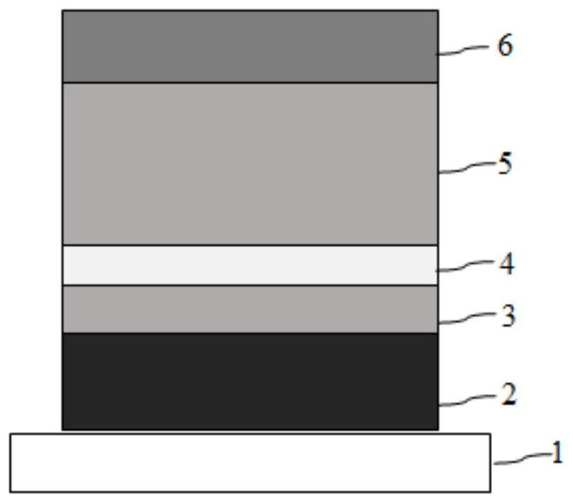
[0053] Such as Figure 3-7 As shown, a vertical magnetic tunnel junction micromachining method based on shape anisotropy. In this embodiment, the number of tilt adjustments of the sample stage 1 in step S2 is one time, and the free layer and the covering layer after etching are in the shape of oblique columns. . details as follows:

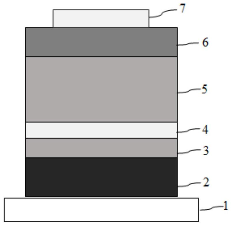
[0054] image 3 It is the process diagram of step S21 , the first mask 7 corresponding to the current inclination angle is fabricated on the cover layer 6 , and the sample stage 1 is at the horizontal position at this time.

[0055] Figure 4 It is the process diagram of step S22, the arrow in the figure indicates the etching direction (for example, the black dot indicates the ion implantation state), the white area surrounded by the dotted line frame is the etched area, and the sample stage 1 is adjusted to the current tilt angle θ 1 , stop when etching down to the free layer 5 and cover layer 6 based on the first mask 7 during processing, an...

Embodiment 2

[0063] Such as Figure 8 As shown, a vertical magnetic tunnel junction micromachining method based on shape anisotropy is based on Embodiment 1, the difference is that in this embodiment, the number of tilt adjustments of the sample stage is one, and the sample stage is also rotated around the second in step S22. The two axes rotate, the second axis is perpendicular to the horizontal plane, and the etched free layer and covering layer are in the shape of oblique columns.

[0064] specifically, Figure 8 It is the process diagram of step S22, the left vertical arrow in the figure indicates the etching direction (such as the black dot indicates the ion implantation state), the white area surrounded by the dotted line frame is the etched area, and the right arrow indicates the The direction of rotation around the second axis. The second axis is perpendicular to the horizontal plane and can be located at any position. It is preferable to make the sample stage 1 occupy a small spa...

Embodiment 3

[0066] Such as Figure 9-12 As shown, a vertical magnetic tunnel junction micromachining method based on shape anisotropy, in this embodiment, the tilt adjustment times of the sample stage is one time, and in step S22, the sample stage also rotates around the third axis, the third axis is The central axis of the first mask is perpendicular to the sample stage, and the etched free layer and cover layer are in the shape of an inverted cone. details as follows:

[0067] In step S21 (not shown in the figure), a first mask 7 corresponding to the current inclination angle is fabricated on the cover layer 6, and the sample stage 1 is at a horizontal position at this time.

[0068] Figure 9 It is the process diagram of step S22, the vertical arrow in the figure indicates the etching direction, the white area surrounded by the dotted line frame is the etched area, and the sample stage 1 is adjusted to the current inclination angle θ 1 , rotate the sample stage 1 during processing t...


PUM

PropertyMeasurementUnit
thicknessaaaaaaaaaa
thicknessaaaaaaaaaa
thicknessaaaaaaaaaa

Abstract

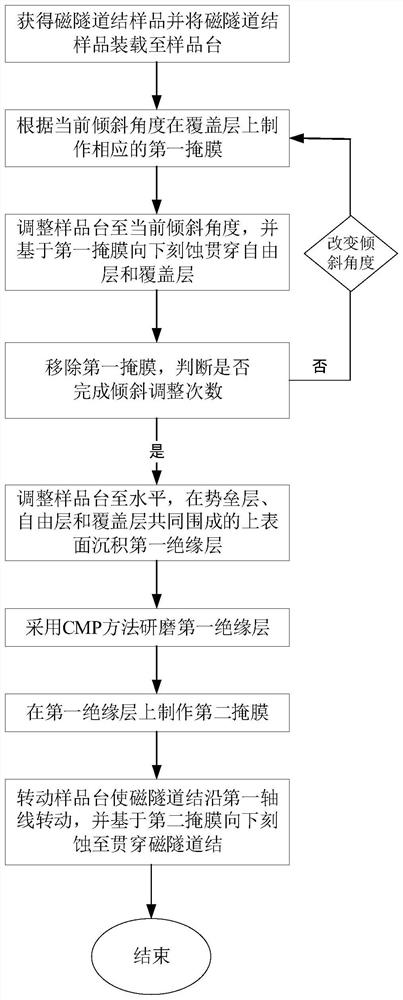
The invention discloses a vertical magnetic tunnel junction micromachining method based on shape anisotropy. The method comprises the steps: acquiring a sample and installing the sample on a sample table; adjusting the inclination of the sample table, determining the inclination adjustment times according to different inclination angles, and etching the magnetic tunnel junction, specifically, manufacturing a corresponding first mask on the covering layer according to the current inclination angle; adjusting the sample table to the current inclination angle, and etching downwards to penetrate through the free layer and the covering layer based on the first mask; removing the current first mask, changing the inclination angle, and returning to manufacture a new first mask until the inclination adjustment times are completed; adjusting the level of the sample stage, and depositing a first insulating layer on the upper surface enclosed by the barrier layer, the free layer and the covering layer; grinding the first insulating layer; manufacturing a second mask on the first insulating layer; rotating the sample table to enable the magnetic tunnel junction to rotate along the first axis, and performing downward etching based on the second mask to penetrate through the magnetic tunnel junction. The method is simple in machining process, high in yield and machining efficiency and suitable for machining of different products.

Description

technical field [0001] The invention belongs to the field of memory technology, and in particular relates to a shape anisotropy-based vertical magnetic tunnel junction micromachining method. Background technique [0002] With the increasing requirements of hardware for memory performance, the magnetic tunnel junction, as the basic storage unit of magnetic memory, directly determines its storage performance. When pursuing the miniaturization and high stability of the device at the same time, it is difficult to achieve ultra-small device size (such as diameter less than 20nm) and high thermal stability at the same time for the magnetic tunnel junction based on the perpendicular anisotropy of the interface. The vertical magnetic tunnel junction based on shape anisotropy solves this problem by utilizing the additional vertical shape anisotropy. However, although the existing general-purpose vertically anisotropic devices solve the problem of thermal stability, they also face th...

Claims


Application Information

Patent Timeline
Patent Type & Authority Applications(China)
IPC IPC(8): H01L43/12H01L43/08H10N50/01H10N50/10
CPCH10N50/01H10N50/10
Inventor 孟皓迟克群张龙龙
Owner CETHIK GRP
Learn More