
Filter assembly with wire harness stable connection effect

A filter and connector technology, which is applied in the field of filters, can solve the problems of accelerating the heat dissipation of heat sinks, the impact of workers' use, and the lack of wiring harness structures, etc., to achieve the effects of avoiding connection errors, ensuring stability, and ensuring tightness

Inactive Publication Date: 2022-02-11
UNIFLIGHT(NANTONG)TECH CO LTD
View PDF8 Cites 2 Cited by
  • Summary
  • Abstract
  • Description
  • Claims
  • Application Information

AI Technical Summary

Problems solved by technology

The aforementioned filter with adjustable inductance can adjust its inductance and increase the scope of application of the filter.” This device lacks a structure to adjust the length of the external sensing line, and the line is too long, which will have a certain impact on the use of workers.
[0005] 2. Patent document CN213816385U discloses a filter with a transmission zero point, "including a bottom box, a top box hinged to the bottom box, and a filter arranged inside the bottom box and the top box; the bottom box A cooling box is fixed at the bottom of the inner side of the box, the filter is placed on the upper surface of the cooling box, a fan is arranged inside the cooling box, and a driving mechanism for driving the fan to rotate is arranged inside the cooling box. There are several groups of heat dissipation holes on the top of the heat dissipation box; the technical problem to be solved by adopting the utility model is to provide a filter with quick disassembly and assembly for heat dissipation, and the heat sink is pushed by the clamping mechanism to fit the filter, and the driving mechanism is controlled at the same time Drive the fan to rotate, accelerate the heat dissipation of the heat sink, and at the same time, the clamping mechanism makes installation and disassembly more convenient." The device lacks a wiring harness structure, resulting in a lack of restraint of the wires, which are scattered outside the device, affecting the use of workers
[0006] 3. The patent document CN214177271U discloses a filter with quick disassembly and assembly function and is convenient for heat dissipation, "comprising a bottom box, a top box hinged to the bottom box, and a filter set inside the bottom box and the top box. A heat sink is fixed at the inner bottom of the bottom box, the filter is placed on the upper surface of the heat sink, a fan is arranged inside the heat sink, and a fan for driving the fan to rotate is arranged inside the heat sink. Drive mechanism, the top of the heat dissipation box is provided with several groups of heat dissipation holes; the technical problem to be solved by adopting the utility model is to provide a filter with quick disassembly and assembly for heat dissipation, and push the heat sink to fit the filter through the clamping mechanism , at the same time control the driving mechanism to drive the fan to rotate, accelerate the heat dissipation of the heat sink, and at the same time, the clamping mechanism makes installation and disassembly more convenient". No real bondage to the line

Method used


Image

  • Filter assembly with wire harness stable connection effect
  • Filter assembly with wire harness stable connection effect
  • Filter assembly with wire harness stable connection effect

Examples


Embodiment 1

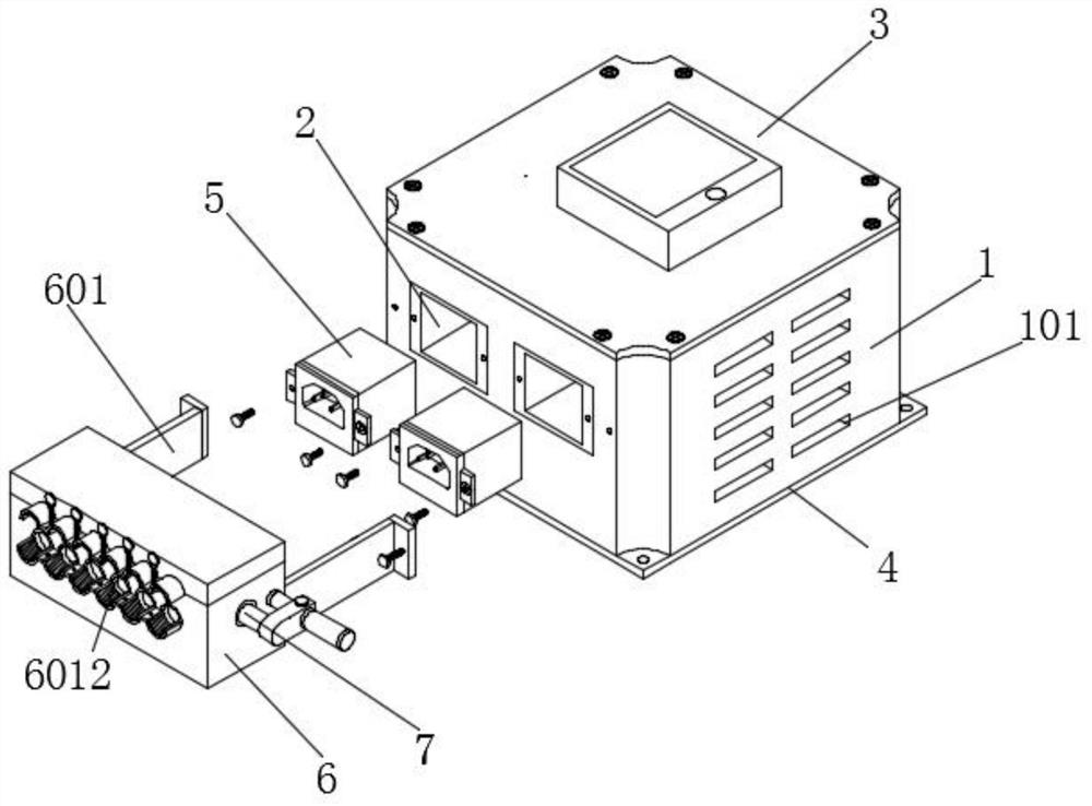
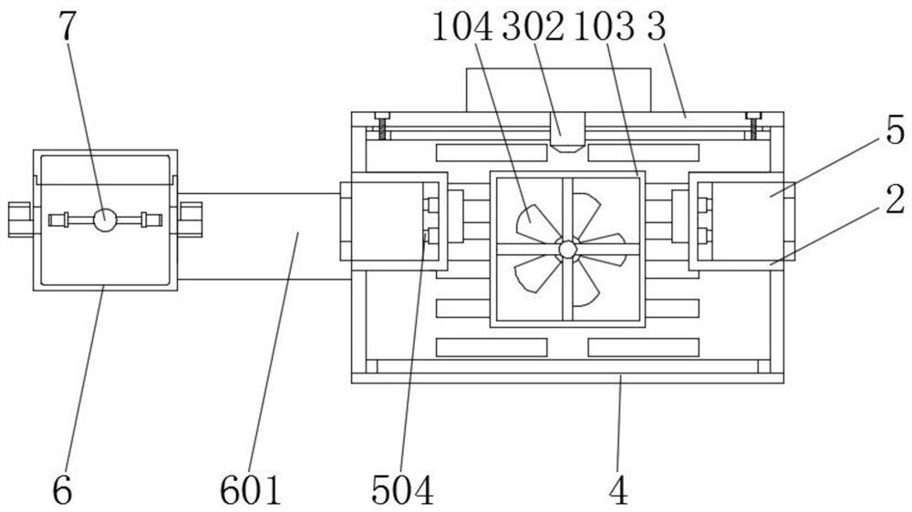
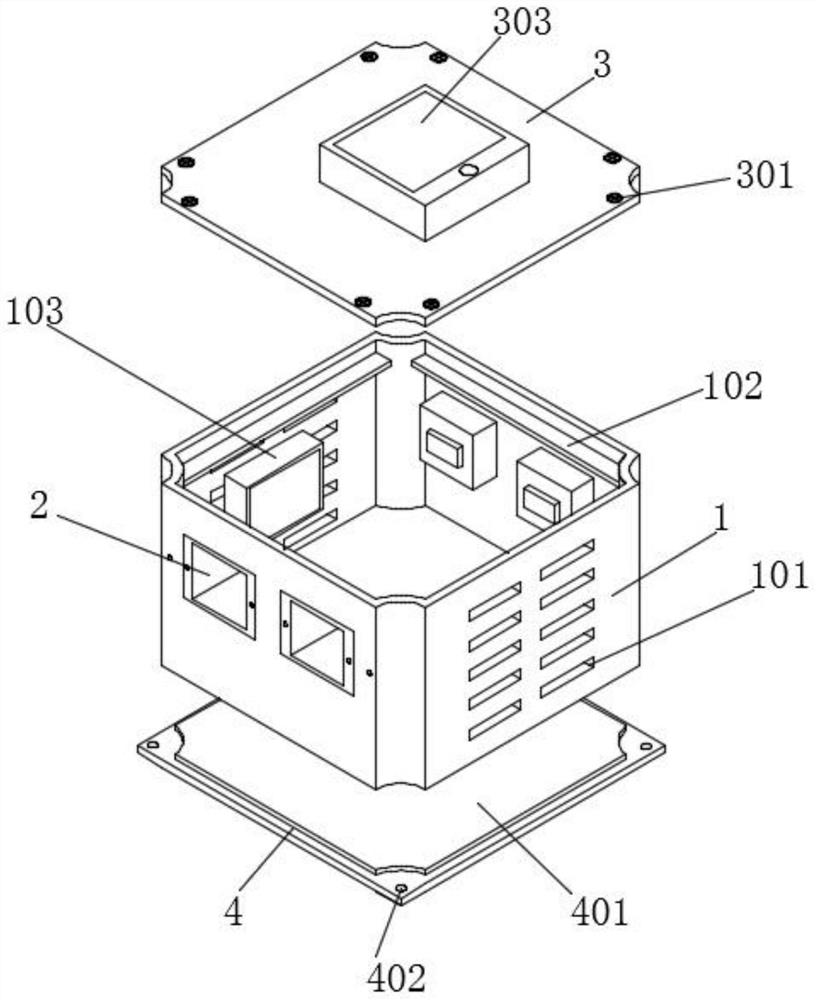
[0042] Embodiment 1 includes a housing 1 and a box body 6. The outer walls of both sides of the housing 1 are provided with cooling vents 101. The cooling vents 101 facilitate the entry of outside air into the interior of the housing 1 to ensure the air transmission of the device. patency, the inner side of the housing 1 is installed with a connecting plate 102, and the connecting plate 102 is located above the heat dissipation port 101 and the fixing groove 2, and the inner side of the housing 1 is installed with a fixed frame 103, and the fixed frame 103 is located at the heat dissipation The inner side of the opening 101, the inner side of the fixed frame 103 is installed with a cooling fan 104, the inner side of the bottom of the housing 1 is fitted with a clip 401, the bottom of the clip 401 is installed with a bottom plate 4, and through the clip 401 Assembling the base plate 4 and the housing 1 is convenient for workers to assemble the device. The inner side of the base ...

Embodiment 2

[0044] The second embodiment includes a housing 1 and a box body 6. Two sets of symmetrically arranged fixing grooves 2 are installed through the front wall and the rear wall of the housing 1, and the inner side of the fixing groove 2 is installed with an electrical connection seat. 201, the fixing groove 2 is fixed on the housing 1 to ensure the stability of the fixing groove 2, and the inner side of the two groups of the fixing grooves 2 is fitted with a connector 5, and the front end of the connector 5 is installed with a mounting cap 501, The front inner side of the installation cap 501 is provided with a docking card slot 505, and two sets of through-boards 502 are installed symmetrically on both sides of the installation cap 501, and connecting screws 503 are installed through the inner sides of the two sets of through-boards 502, and the connecting screws 503 are installed through threads. On the outer wall of the fixing groove 2, the rear end of the connector 5 is equip...

Embodiment 3

[0046] Embodiment 3 includes a housing 1 and a box body 6. The front of the housing 1 is equipped with two sets of symmetrically arranged support plates 601 through bolts, and the support plates 601 are fixed on the front of the housing 1 by bolts to ensure that the support plates 601 stability, and the support plate 601 is located on both sides of the fixing groove 2, the front end of the support plate 601 is installed with a box body 6, and the front and back inner walls of the box body 6 are installed with a wire harness tube 6012, and the transmission line is passed through Through the inner side of the wire harness tube 6012, the wire harness tube 6012 binds the inner sensing line, the front of the wire harness tube 6012 is installed with a fixed snap ring 603, and the inner side of the fixed snap ring 603 is installed with a first anti-skid pad 604, A first fixed plate 605 is installed between the two sets of fixed snap rings 603, a first threaded hole 606 is provided on ...


PUM


Abstract

The invention discloses a filter assembly with a wire harness stable connection effect, and the filter assembly comprises a shell and a box body; a clamping piece is mounted on the inner side of the bottom of the shell in an embedded manner, a bottom plate is mounted at the bottom of the clamping piece, and a top cover is mounted at the top of the shell in an embedded manner; two groups of symmetrically arranged fixing grooves are formed in the front wall and the rear wall of the shell in a penetrating manner, and connectors are mounted on the inner sides of the two groups of fixing grooves in an embedded manner; two sets of symmetrically-arranged supporting plates are installed on the front face of the shell through bolts, and the supporting plates are located on the two sides of the fixing groove. A worker rotates a crank to enable the rotating rod to rotate, the rotating rod rotates to drive a supporting rod on the outer side to rotate, the supporting rod rotates to drive a mounting plate at one end to conduct circular motion, the mounting plate moves to drive an embedding limiting clamping base to move, and the embedding limiting clamping base drives a sensing line to rotate. And the sensing line is wound on the outer side of the mounting plate, so that a worker can conveniently adjust the length of the sensing line in the outside as required.

Description

technical field [0001] The invention relates to the technical field of filters, in particular to a filter component with the effect of stabilizing the connection of wire harnesses. Background technique [0002] The power filter is a filter circuit composed of capacitors, inductors and resistors. The filter can effectively filter the frequency point of a specific frequency in the power line or frequencies other than this frequency point to obtain a power signal of a specific frequency or eliminate a power signal of a specific frequency. [0003] The drawbacks of filter components in the prior art are: [0004] 1. The patent document CN213342159U discloses a filter with adjustable inductance strength, "including: a housing and an inductance component. There is a housing cavity inside the housing, and a threaded hole is opened on the side wall of the housing. The threaded hole and the housing The cavity is connected. The insulating bobbin is accommodated in the accommodating ...

Claims


Application Information

Patent Timeline
Patent Type & Authority Applications(China)
IPC IPC(8): H01P1/30H01P1/20H05K7/20
CPCH01P1/30H01P1/20H05K7/20209
Inventor 秦勇飞汤勇
Owner UNIFLIGHT(NANTONG)TECH CO LTD
Learn More