High-protection-level low-voltage switchgear assembly
A switchgear, low-voltage complete set of technology, applied in the field of high-level low-voltage complete switchgear, can solve problems such as high noise, and achieve the effect of reducing the degree of damage and time
- Summary
- Abstract
- Description
- Claims
- Application Information
AI Technical Summary
Problems solved by technology
Method used
Image
Examples
Embodiment 1
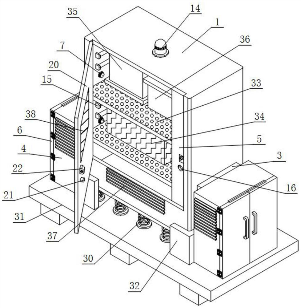
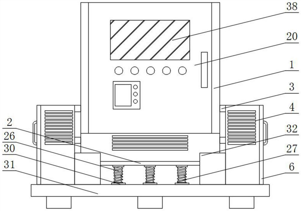
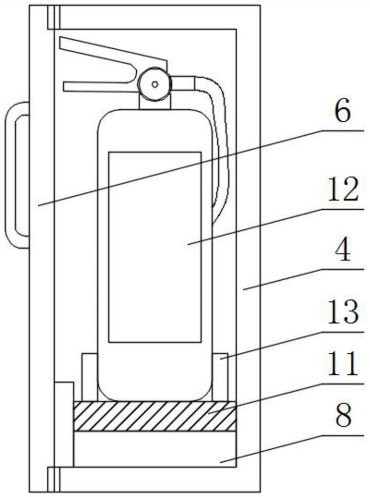
[0044] Such as figure 1 , image 3 with Figure 4 As shown, a low-voltage complete switchgear with high protection level includes a switchgear box 1, an integrated board 2, a connecting block 3, a reserve frame 4 and a baffle 5, and the bottom of the switchgear box 1 is equipped with an integrated board 2;
[0045] Both sides of the switchgear box 1 are equipped with two sets of connecting blocks 3 arranged up and down. The outer wall of the connecting block 3 away from the switchgear box 1 is equipped with a reserve frame 4, and the inner wall of one side of the switchgear box 1 is installed with a baffle. 5;
[0046] Specifically, the switchgear box 1 provides a comprehensive placement space for various components inside it, and increases a certain degree of protection for such components. The comprehensive board 2 is used to connect multiple sets of elastic members, so that it forms a whole, and then it is convenient to connect with the switch. The equipment box 1 is con...
Embodiment 2
[0051] Such as figure 1 with Figure 5 As shown, the inner walls of both sides of the switchgear box 1 are equipped with multiple groups of lighting lamps 15 arranged up and down, the front of the baffle plate 5 is provided with a notch 16, and the inner wall of one side of the notch 16 is equipped with a lighting switch 17, and the lighting switch 17 is electrically connected with the illuminating lamp 15, an extruding spring 18 is installed on the rear wall of the notch 16, and an extruding block 19 is installed on the front of the extruding spring 18.
[0052] Specifically, when the illuminating lamp 15 starts, it can emit light to illuminate the surrounding environment, which can provide convenience for the staff to overhaul the devices inside the switchgear box 1. The installation of 19 provides a comparatively suitable place. When the lighting switch 17 is squeezed, the lighting lamp 15 electrically connected to it can be started. In the closed state, the extrusion spr...
Embodiment 3
[0056] Such as figure 1 , Figure 5 with Image 6 As shown, the back side of the box door 20 is equipped with a locking block 22, and the locking block 22 is located above the pressing column 21, and the front of the baffle plate 5 is provided with a square groove 23, and the square groove 23 is located above the notch 16, A miniature telescopic rod 24 is installed on one side of the outer wall of the baffle plate 5 , and one end of the miniature telescopic rod 24 extends into the inside of the square groove 23 .
[0057] Specifically, one side of the outer wall of the locking block 22 is provided with a slot hole. When the door 20 is closed and the back side of the locking block 22 extends into the square slot 23, the gap between the slot hole and the miniature telescopic rod 24 The center of circle is on the same horizontal line, start the miniature electric extension rod 24 this moment, impel it to carry out outward extension operation, and one end can penetrate the inside ...
PUM
 Abstract
Description
Claims
Application Information
 - R&D
- Intellectual Property
- Life Sciences
- Materials
- Tech Scout
- Unparalleled Data Quality
- Higher Quality Content
- 60% Fewer Hallucinations
Browse by: Latest US Patents, China's latest patents, Technical Efficacy Thesaurus, Application Domain, Technology Topic, Popular Technical Reports.
© 2025 PatSnap. All rights reserved.Legal|Privacy policy|Modern Slavery Act Transparency Statement|Sitemap|About US| Contact US: help@patsnap.com


