
Multifunctional metal plate laser machine rack

A laser machine and multi-functional technology, which is applied in laser welding equipment, metal processing equipment, welding equipment, etc., can solve the problems of unfavorable cleaning, fixation of special-shaped objects, and influence on cutting effect, etc. Effect

Inactive Publication Date: 2022-02-15
苏州刘氏钣金科技有限公司
View PDF1 Cites 0 Cited by
  • Summary
  • Abstract
  • Description
  • Claims
  • Application Information

AI Technical Summary

Problems solved by technology

[0003] And the existing publication number is a disclosed multifunctional sheet metal laser machine frame of CN112008268A, when its laser cutting machine is in use, because the laser beam can produce more metal debris when cutting its object, its The debris is generally melted metal particles, and the laser cutting machine directly sets the inside of the frame in a hollow state for the discharge of debris, which causes the debris to fall to the bottom of the frame, which is not conducive to later cleaning. , when cutting some special-shaped objects, the support frame on the frame cannot stably fix the special-shaped objects, which will affect the cutting effect

Method used


Image

  • Multifunctional metal plate laser machine rack
  • Multifunctional metal plate laser machine rack
  • Multifunctional metal plate laser machine rack

Examples


Embodiment 1

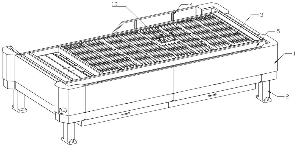
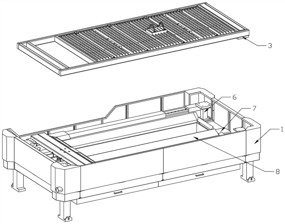
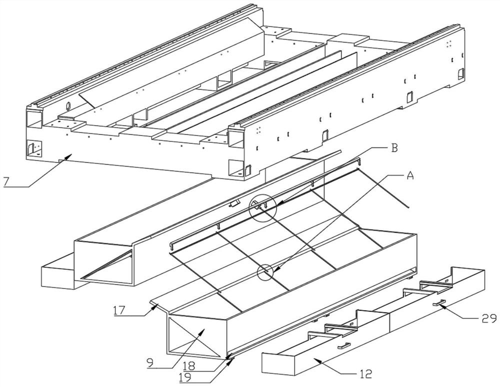
[0030] like Figure 1 - Figure 9 As shown, a multifunctional sheet metal laser frame provided by the present invention includes a frame 1, and a support leg 2 is provided on the bottom of the frame 1, respectively, and the inner wall body of the frame 1 is provided with a support frame. 7, the support frame 7 is provided with a support post 6, respectively, and a support column 6 is provided on the top wall of the support column 6, and a protective bar is also provided on the rear end of the rack 1. 1 The front end and the rear end wall are also provided with a rail 5, and the front end of the support frame 7 and the rear end wall are also provided with the cleaning mechanism 8, and the cleaning mechanism 8 includes a chip box 9, a screw 10, a scraper 11. A support mechanism 13 is further provided on the top of the bracket 3, and the support mechanism 13 includes a fixed stage 14, the mount 15 and the support rod 16.

Embodiment 2

[0032] The two chip chip 9 sides are fixed to one end wall of the support frame 7, respectively, and the two chip chopper 9 is fixedly coupled, and the chip box 9 is below the other side. There is also a divissing port 18 in the wall, and a plurality of fixed blocks 19 are fixedly mounted on both sides of the front end of the chip chopper 9, and there are several slide ports 20 in the bottom wall in the chip box 9, respectively. The bottom portion of the chipboard 9 is also fixed to the corresponding slide 20 on both sides of the wall, respectively, and the cleaning mechanism 8 also includes a motor 22 fixedly mounted on the central position wall of the guide plate 17 bottom. The motor 22 is electrically connected to the controller in the rack 1, and the walls of the screw 10 are each inserted into a fixed bearing mounted on one side wall of the chip chip size 9, and the solenoid of the screw 10 through the chuff The bearing of the side wall of the box 9 extends to the exterior of...

Embodiment 3

[0034]A plurality of card slots 30 are opened in the bottom wall of the fixed stage 14, and the fixing table 14 is mounted on the carriage 3 by the card groove 30, and several first restricted grooves 31 are also opened in the outer wall of the fixed stage 14. The mounting seat 15 bottom wall is fixedly mounted, and the second restrictive block 32 is inserted into the corresponding first-position slot 31, and the second limit block 32 has magnetic, mount 15. A fixed shaft 33 is formed in the two-side wall, and the support rod 16 is fixedly mounted on the bottom wall body, and the fixed shaft 34 is fixed in the corresponding hole 33, and the fixed shaft 34 side wall body is formed. A stopper 35 is also fixed, and a knob block 36 is further provided on the other side of the fixed shaft 34, and the second screw hole 37 is opened in the woven block 36, and the knob block 36 is rotated into the second screw hole 37. A fixing seat 38 is attached to the top wall of the support rod 16, an...


PUM


Abstract

The invention discloses a multifunctional metal plate laser machine rack which comprises a rack, supporting legs are arranged on the peripheral wall bodies of the bottom of the rack, a supporting frame is arranged in the inner side wall body of the rack, supporting columns are arranged on the peripheral wall bodies of the top of the supporting frame and a bearing frame is arranged on the top wall bodies of the supporting columns. A protective fence is further arranged on one side wall body of the rear end of the rack, sliding rails are further arranged on the front end wall body and the rear end wall body of the top of the rack correspondingly, and cleaning mechanisms are further arranged in the front end wall body and the rear end wall body of the supporting frame correspondingly. According to the multifunctional metal plate laser machine rack, by the arrangement of the cleaning mechanism in the scrap collecting box, scraps in the scrap collecting box can be conveniently scraped into the storage box, later cleaning is facilitated, meanwhile, molten metal scraps are prevented from being pasted on the bottom wall body in the scrap collecting box, and in addition, by arrangement of the supporting mechanism capable of being adjusted at multiple angles, objects with different shapes can be conveniently supported and fixed.

Description

Technical field [0001] The present invention relates to the technical field of laser cutting machine devices, and in particular, to a multifunctional sheet metal laser rack. Background technique [0002] The laser cutting machine is a laser beam that will be emitted from the laser, focused laser beam, and the laser beam is irradiated to the surface of the workpiece, so that the workpiece reaches the melting point or boiling point, and the high pressure gas coaxial with the beam will melt or The gasification metal blows away, and the laser cutting process is a conventional mechanical knife with an invisible beam, which has high precision, fast cut, not limited to cutting pattern restrictions, automatic typographic saving materials, smoothing, low processing cost, etc. Features. [0003] A multi-function sheet metal laser frame rack disclosed in CN112008268A is disclosed, and the laser cutting machine is in use, because the laser beam is cut, there is more metal debris when cutting...

Claims


Application Information

Patent Timeline
Patent Type & Authority Applications(China)
IPC IPC(8): B23K26/70B23K26/38
CPCB23K26/702B23K26/38
Inventor 刘汉英
Owner 苏州刘氏钣金科技有限公司
Learn More