Liquid metal 5G filter

A liquid metal and filter technology, applied in waveguide devices, electrical components, circuits, etc., can solve the problems of small size, inconvenient operation, time-consuming and labor-intensive, etc., and achieve the effect of improving service life, convenient fixed installation, and improving stability

Active Publication Date: 2022-02-15
GUANGXI NORMAL UNIV FOR NATITIES
View PDF7 Cites 0 Cited by
  • Summary
  • Abstract
  • Description
  • Claims
  • Application Information

AI Technical Summary

Problems solved by technology

[0004] The purpose of the present invention is to provide a liquid metal 5G filter to solve the problem that the existing traditional filter proposed in the above back

Method used


Image

  • Liquid metal 5G filter
  • Liquid metal 5G filter
  • Liquid metal 5G filter

Examples


Embodiment 1

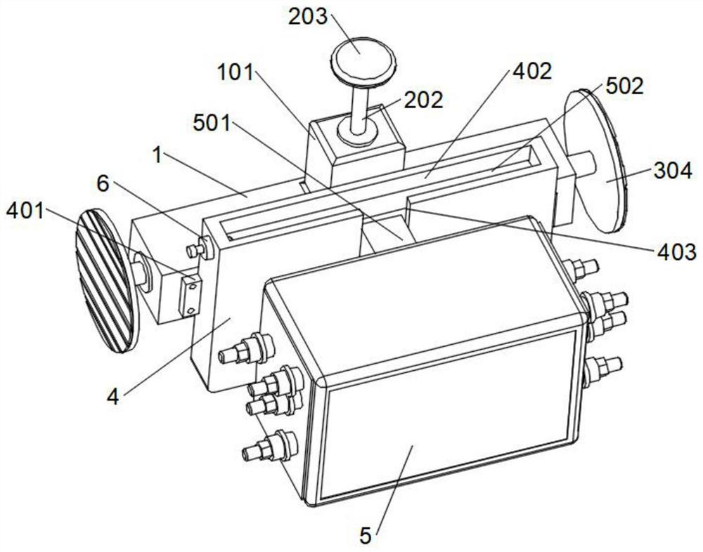
[0033] refer to Figure 1-5 A liquid metal 5G filter shown includes a horizontal frame 1, a mounting block 4 and a filter body 5. An end block 101 is fixedly installed in the middle of the upper surface of the horizontal frame 1, and a propulsion assembly is arranged inside the end block 101. The horizontal frame 1. There are supporting components on both sides of the interior that can be pressure-guided and matched with the propulsion component. The front side of the horizontal frame 1 is provided with a mounting block 4. Two sets of mounting supports 401 are symmetrically fixed on both sides of the mounting block 4, and the mounting block 4 passes through The installation support 401 is fixedly connected with the front side surface of the cross frame 1, the filter body 5 is movably installed on the front side of the installation block 4, and the end column 6 is fixedly installed on the left side surface of the installation block 4 close to the upper surface of the installatio...

Embodiment 2

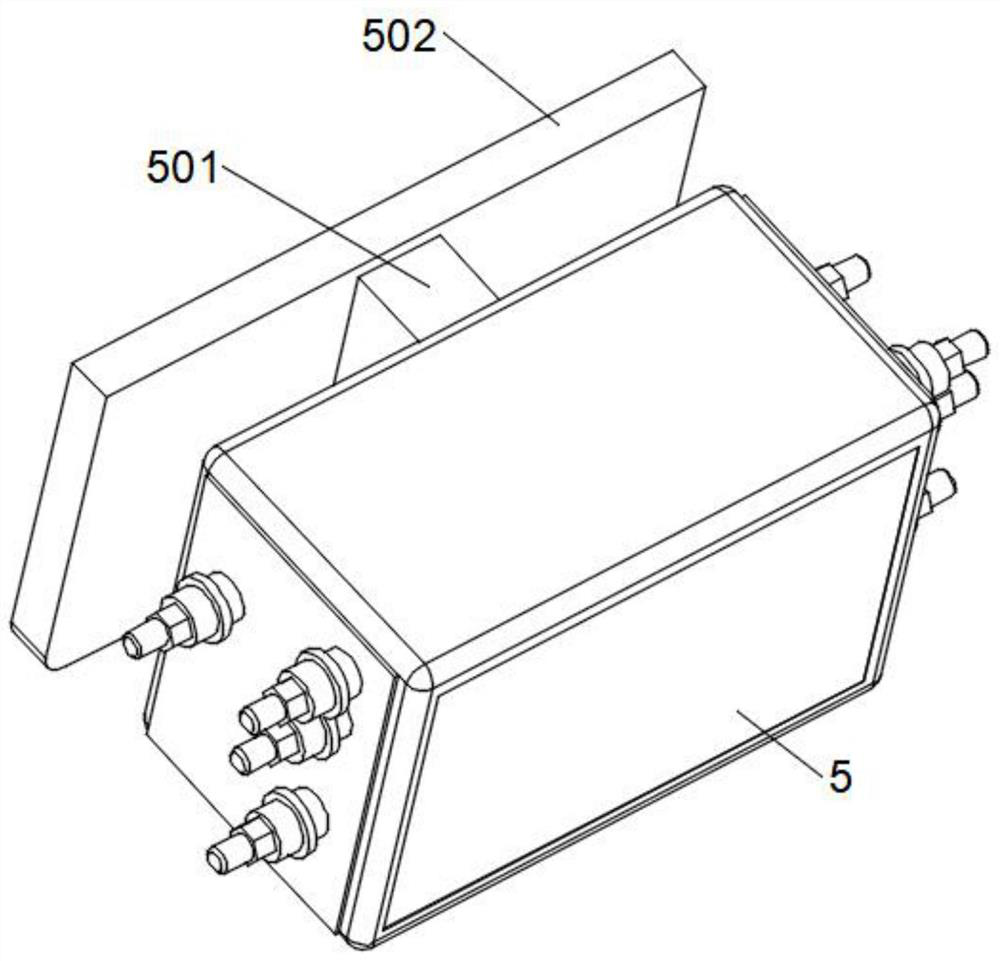
[0036] to combine figure 1 , figure 2 and Figure 4 As shown, based on the above-mentioned embodiment 1, the upper surface of the installation block 4 is provided with a sliding slot 402, and the front surface of the installation block 4 is provided with a relief notch 403, and the relief notch 403 communicates with the sliding slot 402, and the filter The rear surface of the main body 5 is fixedly installed with a connecting fast 501, and the rear surface of the connecting fast 501 is fixedly installed with a sliding mounting plate 502, and the sliding mounting plate 502 is slidably inserted into the sliding slot 402, and the connecting fast 501 is limited and slidably inserted. Align and insert the sliding mounting plate 502 into the sliding slot 402 inside the step-off notch 403. The sliding slot 402 facilitates the insertion of the sliding mounting plate 502, and the step-off notch 403 makes room for connecting the fast 501. snapped in, thereby facilitating the installa...

Embodiment 3

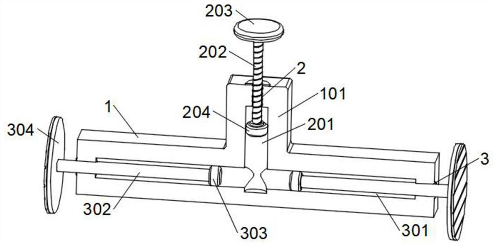
[0038] to combine figure 1 and image 3 As shown, based on the above-mentioned embodiment 1 or 2, the propulsion assembly includes an internally threaded hole 2 opened on the upper surface of the end block 101, and the bottom of the internally threaded hole 2 is provided with a pressure guide hole A201, and the pressure guide hole A201 extends to the cross frame 1, the inner threaded hole 2 is engaged with a threaded rod 202, the upper end of the threaded rod 202 is fixed with a screw cap 203, the end of the threaded rod 202 located in the pressure guide hole A201 is rotated and installed with a piston A204, and the piston A204 is connected to the guide The surface of the inner wall of the pressure hole A201 is slidingly connected, hold the screw cap 203 and twist it, and then drive the threaded rod 202 to rotate to engage with the inner threaded hole 2, and then the threaded rod 202 will push the piston A204 down the inner wall surface of the pressure guiding hole A201 At th...


PUM


Abstract

The invention relates to the technical field of filter mounting devices, in particular to a liquid metal 5G filter. The filter comprises a transverse frame, a mounting block and a filter body; an end block is fixedly mounted in the middle of the upper surface of the transverse frame, a propelling assembly is arranged in the end block, and supporting assemblies capable of being in pressure guide fit with the propelling assembly are arranged on the two sides of the interior of the transverse frame. The filter body can be movably inserted into the front side of the mounting block, the filter body can be fixed through the clamping assembly, and the situation that the filter body falls off can be effectively prevented; meanwhile, the transverse frame can be fixedly mounted between the inner walls of the mounting box through pressure guide fit between the propelling assembly and the supporting assembly, so the filter body is convenient to fix and install, a traditional installation mode that holes are matched with screws is effectively replaced, the trouble brought to installation by an operator due to the fact that the size of the filter body is too small is effectively avoided, and the filter body is convenient to rapidly install and disassemble.

Description

technical field [0001] The invention relates to the technical field of filter installation devices, in particular to a liquid metal 5G filter. Background technique [0002] The filter is the core device of the radio frequency of the base station. Its main function is to make the specific electromagnetic wave phase overlap and offset through the multiple reflection and diffraction of the high-frequency electromagnetic signal in the filter cavity, so as to select the correct frequency, The purpose of filtering clutter, and effectively maintaining the isolation of the receiving and transmitting bands, thereby improving the quality of communication. With the development of 5G technology, 5G filters develop accordingly. Some filters currently on the market use liquid metal as the production medium , which has the advantage of being suitable for high-frequency communications above 6GHz. [0003] The traditional filter is box-shaped. When installing and fixing, it is necessary to ...

Claims


Application Information

Patent Timeline
IPC IPC(8): H01P1/20H01P1/00
CPCH01P1/20H01P1/00Y02P10/20
Inventor 严小黑郑鑫黄设新阮兴祥
Owner GUANGXI NORMAL UNIV FOR NATITIES
Why Eureka
Try Eureka