Eureka AIR delivers breakthrough ideas for toughest innovation challenges, trusted by R&D personnel around the world.

Mixing and tempering bin for burdening

A technology of conditioning and mixing bins, applied in mixers, mixers with rotary stirring devices, applications, etc., can solve the problems of unsatisfactory stirring effect, occupied space, and unsatisfactory effect, and achieve reasonable structure. Stable, increased feeding efficiency, stable structure

Inactive Publication Date: 2022-02-18
扬州市锦标机电设备有限公司
View PDF1 Cites 0 Cited by
  • Summary
  • Abstract
  • Description
  • Claims
  • Application Information

AI Technical Summary

Problems solved by technology

[0003] For example, the patent document with the authorized announcement number: CN2604886Y discloses "a conditioner related to pellet feed processing". The core technical solution of this patent document is to set the overall conditioner as a double-layer cylinder structure, including The upper cylinder and the lower cylinder, the upper cylinder is provided with a feed port, the lower cylinder is provided with a discharge port, and the inside of the upper and lower cylinders are equipped with stirring shafts and paddles. The space occupied by the installation is relatively large, and each cylinder is stirred by a single stirring shaft or a one-way dragon when mixing, so the mixing effect is not very ideal.
[0004] In addition, the conditioner used for feed in the prior art is also equipped with a vertical type. The overall silo is a vertical structure. When the materials are mixed in the silo, due to the gravity of the materials, the mixing time The effect is not ideal

Method used


Image

  • Mixing and tempering bin for burdening
  • Mixing and tempering bin for burdening
  • Mixing and tempering bin for burdening

Examples


Embodiment Construction

[0024] The present invention will be further illustrated below in conjunction with the accompanying drawings and specific embodiments. This embodiment is implemented on the premise of the technical solution of the present invention. It should be understood that these embodiments are only used to illustrate the present invention and are not intended to limit the scope of the present invention.

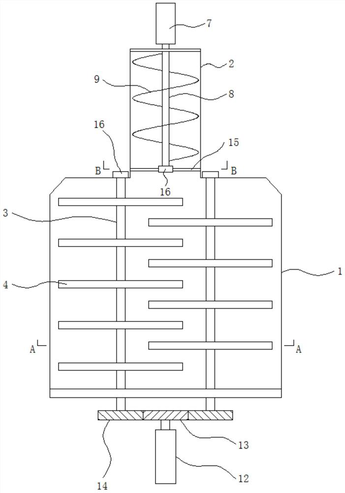
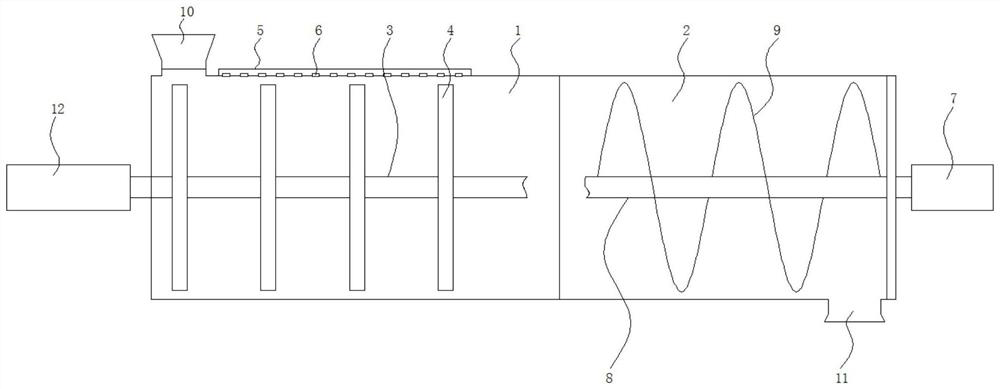
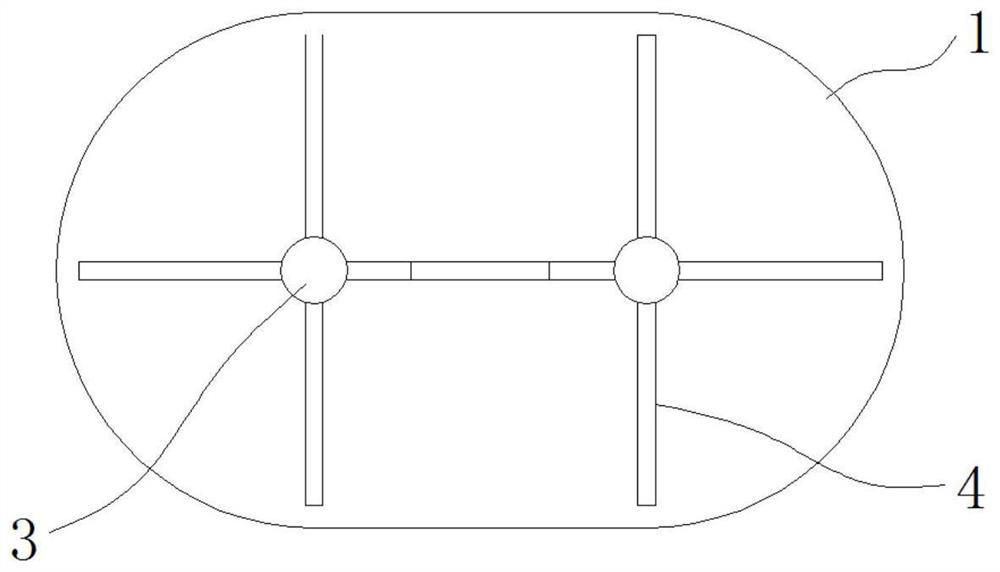
[0025] Such as figure 1 , figure 2 , image 3 and Figure 4 As shown, a mixing and tempering bin for batching includes a double-barrel mixing bin 1 and a single-barrel feeding bin 2; two parallel mixing shafts 3 are installed in the double-barrel mixing bin 1, and on the mixing shaft 3 Evenly spaced mixing rods 4 are installed, and the mixing rods 4 on the two mixing shafts 3 are arranged at intervals, and the mixing rods 4 on one mixing shaft 3 are inserted into the other mixing shaft 3 correspondingly. Between two adjacent mixing rods 4, the front ends of the two mixing shafts 3 s...


PUM


Abstract

The invention discloses a mixing and tempering bin for batching. The mixing and tempering bin comprises a double-barrel mixing bin and a single-barrel feeding bin, wherein two parallel mixing shafts are mounted in the double-barrel mixing bin, mixing rods are mounted on the mixing shafts at uniform intervals, the mixing rods on the two mixing shafts are arranged at intervals, the mixing rods on one mixing shaft are correspondingly inserted between two adjacent mixing rods on the other mixing shaft, and the front ends of the two mixing shafts extend out of the double-barrel mixing bin and are correspondingly provided with driving mechanisms; and the rear ends of the two mixing shafts are correspondingly installed on the inner wall of the rear end of the double-barrel mixing bin, a humidity adjusting water pipe is further installed at the upper end of the double-barrel mixing bin, a water inlet pipe is externally connected to the humidity adjusting water pipe, and downward water spraying holes are formed in the humidity adjusting water pipe. The whole device is of a double-bin body structure, the double-barrel mixing bin at the front end is of a double-barrel type structure, the single-barrel feeding bin at the rear end is of a single-barrel type structure, and mixing and tempering work of ingredients and feeding work of mixed materials after mixing and tempering can be achieved.

Description

technical field [0001] The invention relates to the technical field of batching bin equipment, in particular to a mixing and tempering bin for batching. Background technique [0002] In the prior art, the batching device is widely used in various fields such as chemical industry, medical treatment, machinery, metallurgy, food, etc., and is mainly used for the batching ratio of each component. In the prior art, in the batching process, each material passes through After the weighing device is weighed, it needs to be mixed and tempered, and adjusted to the appropriate humidity, temperature and other devices by heating or water injection, which is suitable for storage or transportation. The structure of the tempering bin in the prior art is usually relatively simple It is usually used as conditioning by setting up a screw pusher. [0003] For example, the patent document with the authorized announcement number: CN2604886Y discloses "a conditioner related to pellet feed process...

Claims


Application Information

Patent Timeline
Patent Type & Authority Applications(China)
IPC IPC(8): B01F27/706B01F27/191B01F27/213B01F35/71B01F35/75A23N17/00
CPCA23N17/007
Inventor 朱彪汤怀斌季长健
Owner 扬州市锦标机电设备有限公司
Why Eureka
Eureka Blog
Learn More