
Eureka
For R&D, Eureka makes reading and utilizing patents & technical documents easy.
Eureka AIR
Designed for self-driven R&D workflows. Generate viable solutions, solve complex R&D challenges, empower your innovation with AI.

Eureka Materials
Designed for material experts only. Revolutionize your material R&D, from search, analyze, to developing new materials.

TechResearch
Generate reliable direction feasibility study reports for your R&D in just a few steps.

TechSeek
Discover and master advanced knowledge NOW. Basics, ideas, possibilities, all at once.

TechMind
As an expert in R&D Theories, TechMind can generates customized viable solutions instantly.

TechRisk
Analyze your overall solution with one click, know your potential R&D risks in advance.

TechMonitor
Get weekly tech updates, stay abreast of the latest tech innovations and key insights.
Metallurgical low-melting-point metal powder hot melting forming equipment
A low-melting-point metal and hot-melt molding technology, which is applied in casting molding equipment, metal processing equipment, casting equipment, etc., can solve the problems of low safety and low work efficiency, reduce labor intensity, prevent hot air loss, and avoid splashing Effect
- Summary
- Abstract
- Description
- Claims
- Application Information
AI Technical Summary
Problems solved by technology
Method used
Image

Examples
Embodiment 1
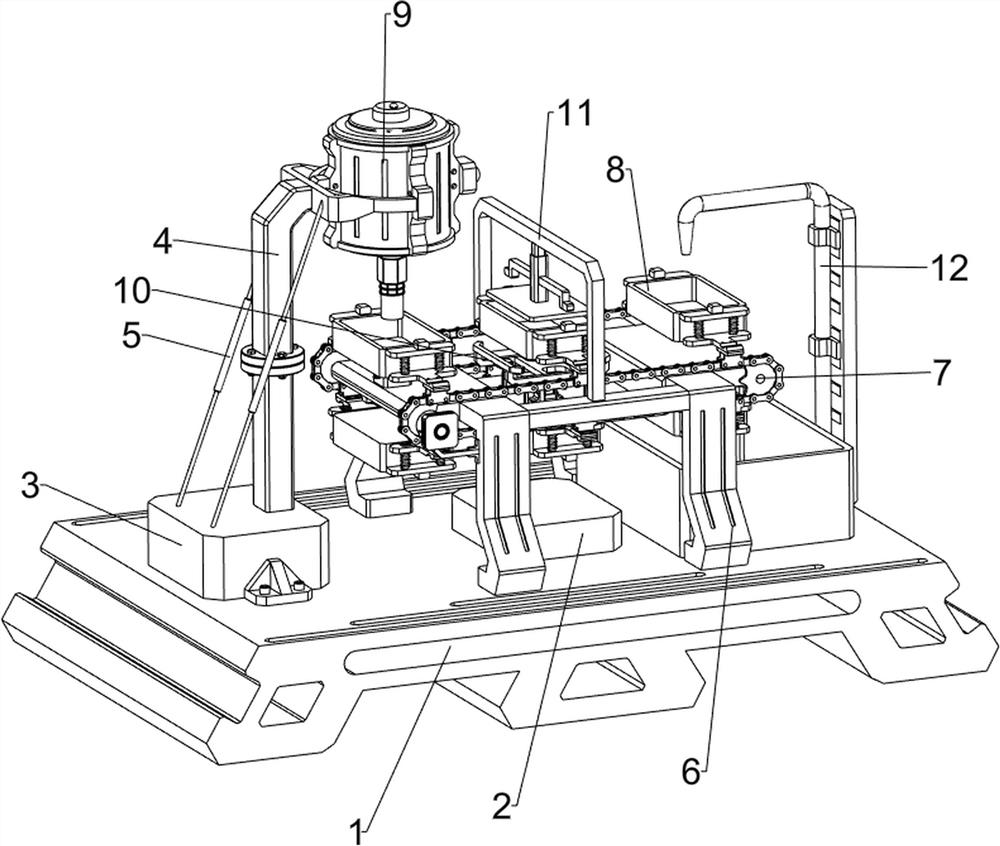
[0031] A metallurgical low melting point metal powder hot melt molding equipment, such as Figure 1-3 As shown, it includes a base 1, a first fixed block 3, a support rod 4, a rope 5, a tripod 6, a transmission mechanism 7 and a bearing mechanism 8, the left side of the top of the base 1 is provided with a first fixed block 3, and the first fixed block 3. The right side of the top is provided with a support rod 4, and a rope 5 is provided symmetrically between the upper left side of the support rod 4 and the left side of the top of the first fixed block 3. A transmission mechanism 7 is connected between them, and a bearing mechanism 8 is connected between the foot frame 6 and the parts of the transmission mechanism 7 .
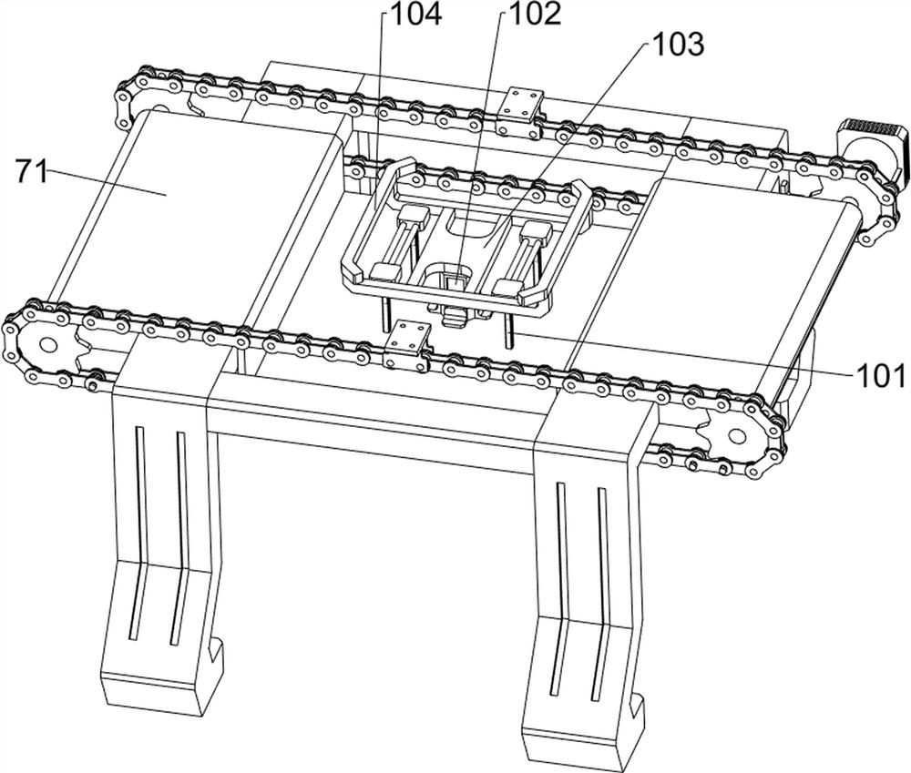
[0032] Transmission mechanism 7 comprises bearing base plate 71, rotating shaft 72, chain 73, drive motor 74, first mounting block 75 and pressure sensor 76, is provided with bearing base plate 71 between tripod 6 tops, and bearing base plate 71 left and right...
Embodiment 2
[0036] On the basis of Example 1, such as Figure 4-9As shown, a blanking mechanism 9 is also included, and the blanking mechanism 9 includes a fixed ring 91, an outer wall of the mechanism 92, a top cover 93, a dust sensor 94, an LED indicator light 95, a solenoid valve 96, a mechanism liner 97, and a swivel ring 98 With the first telescopic rod 99, the right side of the upper part of the support rod 4 is provided with a fixed ring 91, the inner side of the fixed ring 91 is provided with a mechanism outer wall 92, and the top of the mechanism outer wall 92 is threadedly equipped with a top cover 93, and the middle part of the top cover 93 is provided with a dust sensor 94 , the right side of the mechanism outer wall 92 is provided with an LED indicator light 95, the bottom of the mechanism outer wall 92 is provided with a discharge port, the middle part of the discharge port is provided with a solenoid valve 96, the mechanism outer wall 92 is provided with a mechanism liner 97...
PUM
 Abstract
Description
Claims
Application Information
 - R&D Engineer
- R&D Manager
- IP Professional
- Industry Leading Data Capabilities
- Powerful AI technology
- Patent DNA Extraction
Browse by: Latest US Patents, China's latest patents, Technical Efficacy Thesaurus, Application Domain, Technology Topic, Popular Technical Reports.
© 2024 PatSnap. All rights reserved.Legal|Privacy policy|Modern Slavery Act Transparency Statement|Sitemap|About US| Contact US: help@patsnap.com