Gasification ratio-adjustable biomass composite combustion machine
A biomass and burner technology, which is applied in the direction of solid fuel combustion, combustion methods, and controlled combustion, can solve the problems of high cost, low cost, and high nitrogen-containing gas emissions, so as to improve heat use efficiency and gasification Effect, the effect that the manufacturing cost is low
- Summary
- Abstract
- Description
- Claims
- Application Information
AI Technical Summary
Problems solved by technology
Method used
Image

Examples
Embodiment Construction
[0016] A biomass compound burner with adjustable gasification ratio of the present invention will be further described in detail below in conjunction with the accompanying drawings.
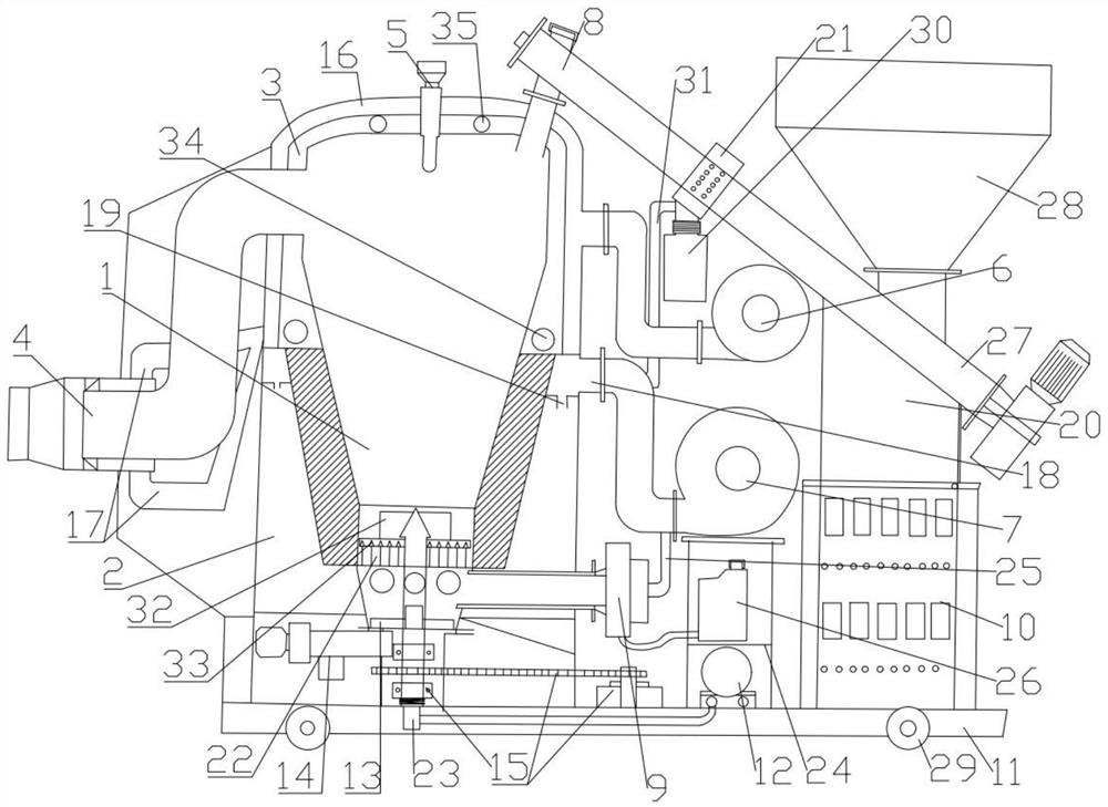
[0017] combined with figure 1 , a biomass composite burner with adjustable gasification ratio, including a combustion furnace 1, a furnace shell 2, a cooling chamber 3, a low nitrogen burner 4, a temperature control thermocouple 5, a first fan 6, a second fan 7, Feeding pipe 8, feeding device, diesel igniter 9, control cabinet 10, base 11, vortex air pump 12, automatic slag discharge device 13, automatic ash unloader 14 and ash and slag removal mechanism 15, the furnace shell 2 is set On the base 11, the lower half of the combustion furnace 1 is arranged in the furnace casing 2, the cooling chamber 3 is arranged around the upper half of the combustion furnace 1 outside, and the lower end of the cooling chamber 3 is arranged at the upper end of the furnace casing 2, The outer periphery of the coo...
PUM
 Abstract
Description
Claims
Application Information
PatSnap Eureka turns technology decisions into work you can execute. Powered by our Innovation Knowledge Graph, it runs expert workflows across engineering, life sciences, materials and intellectual property. Get your review-ready output in minutes.


