Electromagnetic coupling vibration test system and control strategy during high-speed rotation of direct-drive hub motor

An in-wheel motor and electromagnetic coupling technology, which is applied in the field of direct-drive in-wheel motor controller test systems and control strategies, can solve problems such as reduced vehicle ride comfort and vehicle ride comfort affecting occupant comfort.

Pending Publication Date: 2022-02-18
HARBIN UNIV OF SCI & TECH
View PDF0 Cites 2 Cited by
  • Summary
  • Abstract
  • Description
  • Claims
  • Application Information

AI Technical Summary

Problems solved by technology

At present, the virtual instrument has become the main application platform in the field because of its advantages of reducing the cost of actual measurement, real-time detection, and graphical interface. The vibration caused by the deformation of the rotor and stator due to the electromagnetic force of the uneven air gap magnetic field inside the hub motor Electromagnetic coupling vibration is formed between the vibration caused by the change of the magnetic field caused by the change of the electric field. The vibration caused by the change of the wheel hub due to the change of the road surface excitation and the magnetic vibration caused by the change of the internal winding current of the wheel hub caused by the change of the road surface excitation form an electromechanical coupling problem. The target collected by the virtual instrument Mainly concentrated in the normal working range of the hub motor, but when the hub motor is running at high speed, the external road surface of the hub is excited, the electromechanical coupling between the current voltage inside the hub motor and the air gap magnetic field inside the hub motor changes rapidly, so that the smoothness of the car The ride comfort of the car directly affects the comfort of the occupants, so it is of great significance for how to reduce the vibration problem caused by the electromagnetic coupling of the in-wheel motor

Method used


Image

  • Electromagnetic coupling vibration test system and control strategy during high-speed rotation of direct-drive hub motor
  • Electromagnetic coupling vibration test system and control strategy during high-speed rotation of direct-drive hub motor
  • Electromagnetic coupling vibration test system and control strategy during high-speed rotation of direct-drive hub motor

Examples


Embodiment approach

[0040] In this embodiment, the specific implementation process includes the following steps:

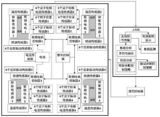
[0041] Step S1: Set the parameter information of the drum, obtain the required torque, input the speed and torque, and send a control command through the vehicle controller to complete the process of starting the vehicle rotation.

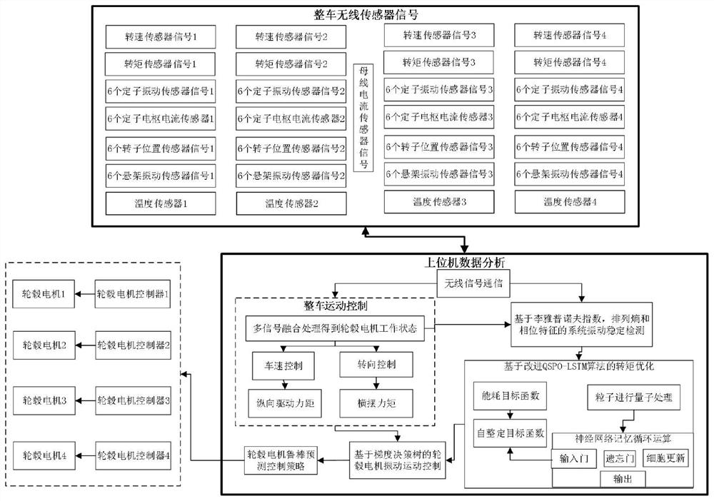
[0042] Step S2: The sensor module detects the working status of the wheel drive in real time. On the one hand, the information is transmitted to the acquisition system through wireless Bluetooth, and then to the data analysis system; on the other hand, the information of the wheel motor is fed back to the wheel motor controller. Control the rotation of the hub motor.

[0043] Step S3: The vibration stabilization layer in the data analysis system processes and calculates the fusion signal. The data is randomly sampled, the phase characteristics are obtained through the time series diagram, and the Lyapunov index and permutation entropy are calculated.

...


PUM


Abstract

The invention relates to an electromagnetic coupling vibration test system and a control strategy during high-speed rotation of a direct-drive hub motor, belongs to the field of magnetic field detection, and solves the problem that an air-gap magnetic field of the hub motor is not easy to detect in a complex working environment. The detection system comprises an upper computer and a whole vehicle experiment bench. Six wireless vibration sensors are embedded in a stator rack in a hub of the whole vehicle experiment bench, six stator armature current sensors are embedded in a stator coil, and six wireless position sensors are embedded in a rotor; and six vibration sensors are respectively embedded into the connecting parts of four driving wheels and a suspension. The upper computer establishes communication connection with a whole vehicle hub driving experiment bench sensor through wireless Bluetooth, and the interior of the upper computer is composed of a hub motor prediction robust controller, a graphical interface, an improved QSPO-LSTM torque optimization algorithm, vibration feature analysis, a gradient lifting decision tree and a series of software designs. And the rotating speed control problem caused by electromagnetic coupling vibration during high-speed rotation of the hub motor is solved through data processing by the upper computer.

Description

technical field [0001] The present application relates to the field of direct-drive hub motor controller test system and control strategy, and more specifically relates to the electromagnetic coupling vibration test system and control strategy of direct-drive hub motor during high-speed rotation. Background technique [0002] Due to the special structure of the hub motor, the complex working environment, and the complex and changeable impact vibration, the distribution of the air gap magnetic field formed between the rotor winding, the stator winding and the permanent magnet after power-on is uneven, and the internal current harmonics are many. Changes, resulting in complex coupling motion inside, the vibration analysis and detection of the coupling motion on the vehicle is an important research direction at present. At present, the virtual instrument has become the main application platform in the field because of its advantages of reducing the cost of actual measurement, r...

Claims


Application Information

Patent Timeline
Patent Type & Authority Applications(China)
IPC IPC(8): G01M7/02G01R31/34H02K11/20H02K11/21H02K11/25H02K11/33
CPCG01M7/02G01R31/34H02K11/21H02K11/25H02K11/20H02K11/33
Inventor 吴石车翠茹李怡鹏管诣博王延福
Owner HARBIN UNIV OF SCI & TECH
Why Eureka
Try Eureka