
Storage system, storage controller and storage chip

A storage system and memory technology, applied in the field of storage controller and a storage chip, storage system, can solve the problems of less switching signals, reduction of the maximum bandwidth of the bus, etc., and achieve the effect of reducing the bus width, increasing the transmission rate and the number of signals

Pending Publication Date: 2022-02-18
ETRON TECH INC
View PDF0 Cites 0 Cited by
  • Summary
  • Abstract
  • Description
  • Claims
  • Application Information

AI Technical Summary

Problems solved by technology

But as the number of signals decreases, the maximum bandwidth of the bus also decreases, for a given switching speed: only fewer switching signals are used to transmit information

Method used


Image

  • Storage system, storage controller and storage chip
  • Storage system, storage controller and storage chip
  • Storage system, storage controller and storage chip

Examples


Embodiment Construction

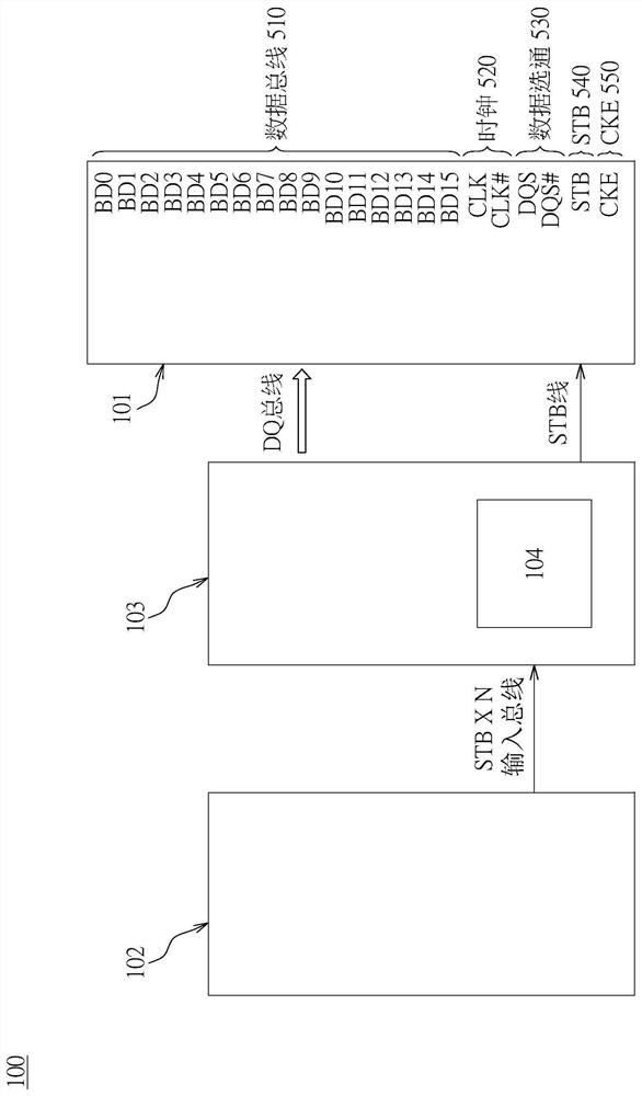
[0044] Please refer to figure 2 , figure 2 is a schematic diagram of the storage system 100 disclosed in the first embodiment of the present invention. Such as figure 2 As shown, the storage system 100 includes a memory 101 , a controller IC 102 , and a physical layer 103 . The controller IC 102 can be coupled to other devices or processors through an Advanced Extensible Interface (AXTI) bus. The advanced scalable interface bus includes a write data bus and a read data bus. The physical layer 103 is electrically connected to the controller IC 102 , and the physical layer 103 is also electrically connected to the memory 101 . Command signals sent by the controller IC 102 need to be converted into a transmission format conforming to the bus of the memory 101 through the physical layer 103, and then transmitted to the memory 101 for execution.

[0045] In this embodiment of the invention, the bus of the memory 101 includes a data bus 510 , a clock 520 , a data strobe 530 ...


PUM


Abstract

The invention discloses a storage system. A storage system includes a memory, a controller, and a physical layer. The memory comprises a data bus and an STB gate with a single pin, and the memory receives a parallel command by using the data bus and receives a serial command by using the STB gate. The physical layer converts STB input data sent by the controller into a serial command, and the serial command is transmitted to the memory through the STB gate.

Description

technical field [0001] The invention relates to a storage system, a storage controller and a storage chip, in particular to a storage system and a storage chip capable of parallel and serial transmission of data between the storage controller and the storage chip. Background technique [0002] Today, memory systems used in high-performance computing or artificial intelligence systems typically include dynamic random access memory chips and logic circuits. Due to the stack structure of the DRAM chip, the size of the DRAM chip cannot keep up with the size of the logic circuit. Therefore, a memory-wall effect occurs, resulting in a decrease in the data transfer rate between the logic circuit and the DRAM chip. In order to overcome the storage wall effect, the prior art usually uses a faster data rate (for example, from double data rate three (DDR3) to double data rate fourth (DDR4) or double data rate fifth (DDR5)) in the transfer data between the dynamic random access memory...

Claims


Application Information

Patent Timeline
Patent Type & Authority Applications(China)
IPC IPC(8): G06F13/16G06F13/38G06F13/40
CPCG06F13/1668G06F13/382G06F13/4068G06F13/423G06F13/4291G06F13/1689G06F13/1678
Inventor 夏濬
Owner ETRON TECH INC
Learn More