Tail end wire stripping machine for high-power transmission cable

A technology for conveying cables and stripping machines, which is used in cable installation, equipment for dismantling/armored cables, cable installation devices, etc. and other problems, to achieve the effect of convenient cutting of insulating protective layer, simple peeling and simple structure

Pending Publication Date: 2022-02-18
ZHEJIANG ZHOUSHAN QIMING POWER CONSTR CO LTD
View PDF7 Cites 0 Cited by
  • Summary
  • Abstract
  • Description
  • Claims
  • Application Information

AI Technical Summary

Problems solved by technology

[0002] In the life of modern people, electricity is an indispensable energy source. During the transmission of electricity, there will inevitably be a butt joint of high-power transmission cables, which is to connect the auxiliary line to the main line through the chuck. In the early stage of connection, The cable needs to be stripped. The existing technology basically handles the position manually. Because the diameter of the high-power transmission cable is large, and the insulation protection layer of the cable is integrally formed by casting during the production process, the labor intensity of stripping is very high. At the same time The docking of high-power transmission cables is done outdoors, and the portable equipment should not be too large, so it is particularly important to design a device that is convenient for stripping wires at the equipment site

Method used


Image

  • Tail end wire stripping machine for high-power transmission cable
  • Tail end wire stripping machine for high-power transmission cable
  • Tail end wire stripping machine for high-power transmission cable

Examples


Embodiment Construction

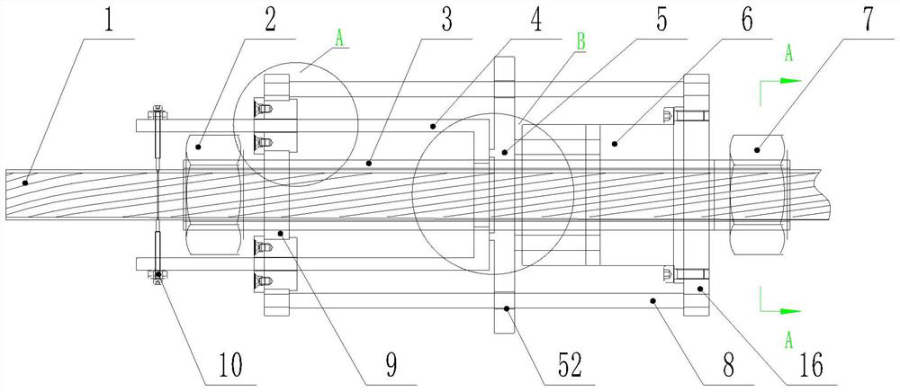
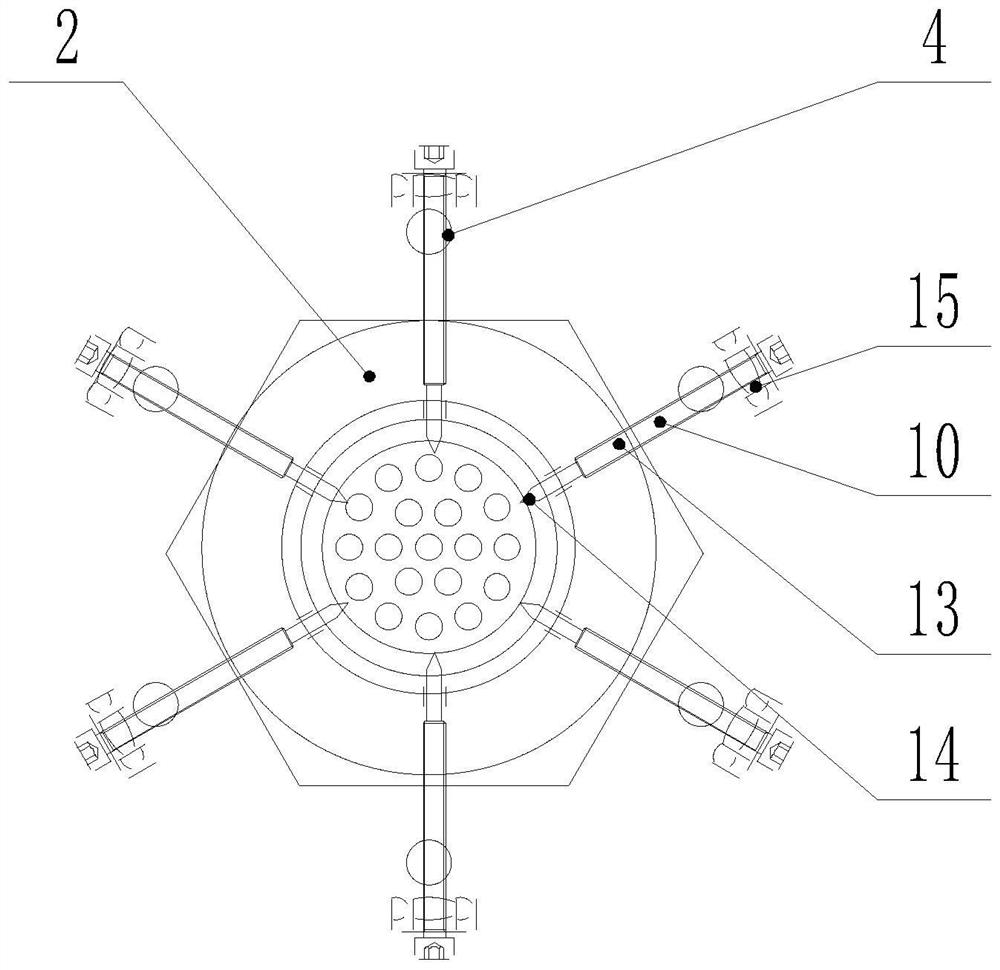
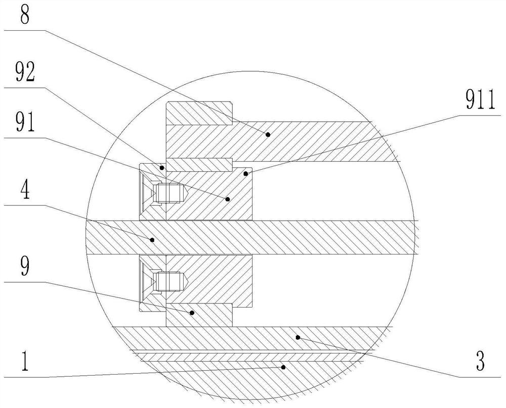
[0025] Such as Figure 1-7 As shown, the terminal stripping machine of a high-power transmission cable according to the present invention includes a fixed sleeve 3, and the two ends of the fixed sleeve 3 are processed with threads, and grooves 31 are processed along the radial direction at the thread. There are lock nut A2 and lock nut B7, through the screwing of lock nut A2 and lock nut B7, the thread is tightened at the groove 31, and the cable 1 is positioned; the positioning plate is fixedly installed on the left side of the fixing sleeve 3 A9, the positioning plate B16 is fixedly installed on the right side, and the positioning plate A9 and the positioning plate B16 are connected by a fixed rod 8. The fixing sleeve 3 is tubular, and the diameter of the inner hole is larger than that of the cable 1. A groove 31 is processed on the outer surface of the fixing sleeve 3. The shape of the groove 31 is helical, and the shape of the helix is ​​consistent with the winding rule of...


PUM


Abstract

A tail end wire stripping machine for a high-power transmission cable comprises a fixing sleeve which is sleeved outside the cable and is positioned through a locking nut, positioning plates which are fixedly connected with two ends of the fixing sleeve, an annular cylinder which is fixed on the positioning plate on the right side, and a positioning ring which is movably installed on the positioning plate on the left side, and a fixing rod which is connected between the positioning plates. A thrust block is sleeved on the fixing sleeve, a thrust disc with a thrust rod is arranged on the left side of the thrust block, and the small-diameter position of the thrust disc is in contact with the groove of the fixing sleeve. Thrust of the annular air cylinder is transmitted through the thrust block to push the thrust rod to move leftwards in a spiral mode, the tool bit installed on the thrust rod cuts an insulation protection layer into spiral strips, and the spiral strips are removed through the peeling ring. The machine is simple in design and convenient to install and operate, replaces existing manual wire stripping, improves working efficiency, is particularly suitable for outdoor operation of operators, and has good practical application value.

Description

technical field [0001] The invention relates to a wire stripping machine, in particular to an end stripping machine for high-power transmission cables. Background technique [0002] In the life of modern people, electricity is an indispensable energy source. During the transmission of electricity, there will inevitably be a butt joint of high-power transmission cables, which is to connect the auxiliary line to the main line through the chuck. In the early stage of connection, The cable needs to be stripped. The existing technology basically handles the position manually. Because the diameter of the high-power transmission cable is large, and the insulation protection layer of the cable is integrally formed by casting during the production process, the labor intensity of stripping is very high. At the same time The docking of high-power transmission cables is done outdoors, and the portable equipment should not be too large. Therefore, it is particularly important to design a...

Claims


Application Information

Patent Timeline
Patent Type & Authority Applications(China)
IPC IPC(8): H02G1/12
CPCH02G1/1268
Inventor 熊安张汉斌田晖洪耀峰王刚黄斌娄凌杰曹雷邱千里潘利明刘阳王信学贺斌周天路陈鼎立
Owner ZHEJIANG ZHOUSHAN QIMING POWER CONSTR CO LTD
Why Eureka
Try Eureka