Engine connection structure of hybrid transmission
A technology of hybrid power and connection structure, which is applied to the layout of multiple different prime movers, clutches, power devices, etc. of general power devices, which can solve problems such as vibration and noise, and achieve the effect of preventing tooth surface clearance
- Summary
- Abstract
- Description
- Claims
- Application Information
AI Technical Summary
Problems solved by technology
Method used
Image
Examples
no. 1 example
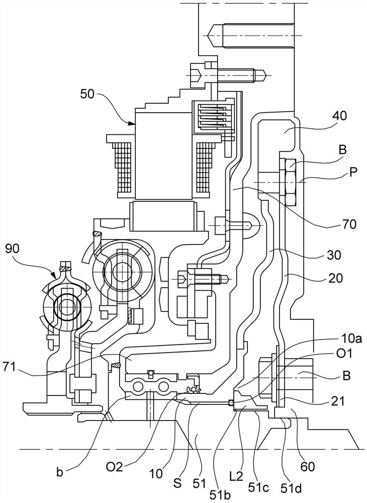
[0039] figure 2 is a diagram showing an engine connection structure of a hybrid transmission according to a first embodiment of the present invention. like figure 2 As shown, the first embodiment of the present invention includes: a connection mechanism, which is formed by a first connection nut 10 connected to the rotating shaft 51 of the motor 50 and connected to the mass block 40 at the same time; the drive plate 20 is used to connect the mass block 40 with the crankshaft 60 of the engine.
[0040] Specifically, the first connecting nut 10 is connected to the outer diameter of the rotating shaft 51 through a spline S.
[0041] When assembling the first connecting nut 10 and the rotating shaft 51 , the surface of the first connecting nut 10 facing the crankshaft 60 is aligned with the lock end portion 51 b of the rotating shaft 51 to form a plane.
[0042]When the first connecting nut 10 is connected to the rotating shaft 51 , the locking nut L2 is connected to the part...
no. 2 example
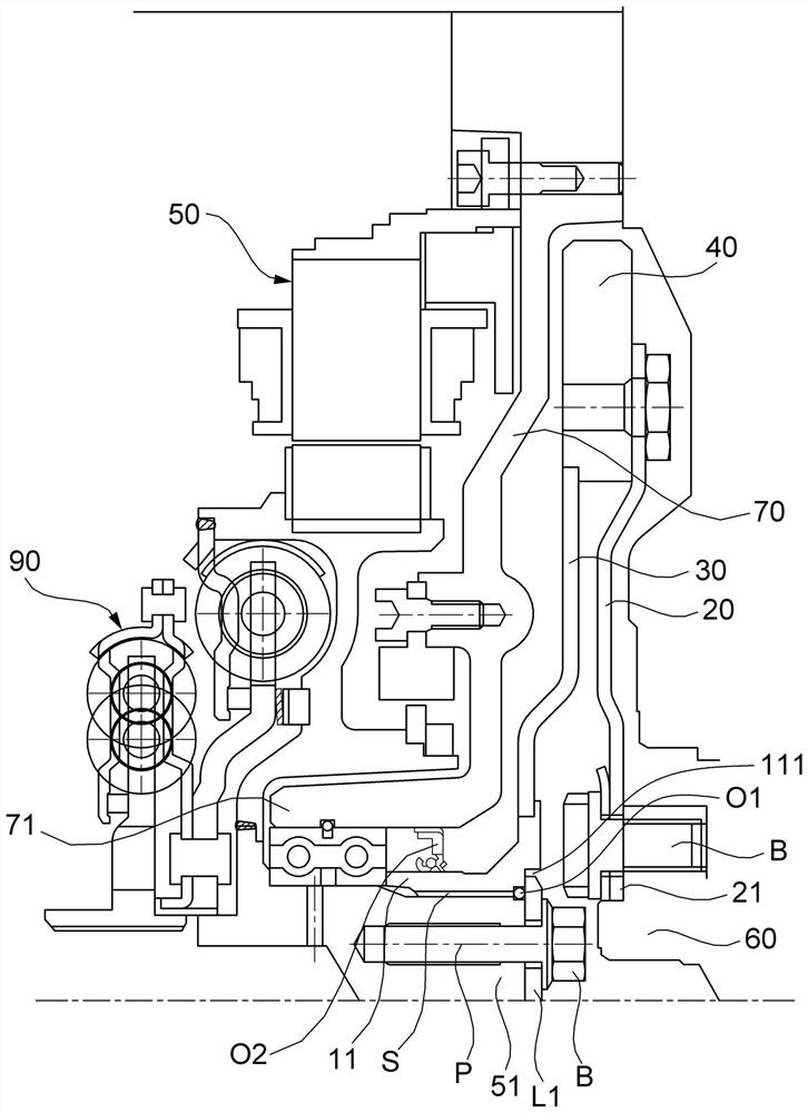
[0062] image 3 is a diagram showing an engine connection structure of a hybrid transmission according to a second embodiment of the present invention. like image 3 As shown, the second embodiment of the present invention includes: a connection mechanism, which is formed by a second connection nut 11 whose edge is connected to the mass block 40 while being connected to the rotating shaft 51 of the motor 50; the driving plate 20 is used to connect the mass block 40 with the crankshaft 60 of the engine.
[0063] Specifically, the second connecting nut 11 is connected to the outer diameter of the rotating shaft 51 through a spline S.
[0064] In a state where the second coupling nut 11 is coupled to the rotation shaft 51 , the bolt B is coupled to the surface facing the rotation shaft 51 of the crankshaft 60 . When assembled, the surface of the crankshaft 60 facing the rotating shaft 51 and the surface of the crankshaft 60 facing the second connecting nut 11 are consistent to...
PUM
 Abstract
Description
Claims
Application Information
 - R&D
- Intellectual Property
- Life Sciences
- Materials
- Tech Scout
- Unparalleled Data Quality
- Higher Quality Content
- 60% Fewer Hallucinations
Browse by: Latest US Patents, China's latest patents, Technical Efficacy Thesaurus, Application Domain, Technology Topic, Popular Technical Reports.
© 2025 PatSnap. All rights reserved.Legal|Privacy policy|Modern Slavery Act Transparency Statement|Sitemap|About US| Contact US: help@patsnap.com


