Method and system for thin layer depiction

A thin layer, weight coefficient technology, applied in measurement devices, instruments, scientific instruments, etc., can solve the problems of inversion accuracy limitation, time-consuming calculation, excessive condition number, etc., to improve longitudinal resolution and direct inversion stability. , the effect of improving the accuracy

Pending Publication Date: 2022-02-22
CHINA PETROLEUM & CHEM CORP +1
View PDF0 Cites 0 Cited by
  • Summary
  • Abstract
  • Description
  • Claims
  • Application Information

AI Technical Summary

Problems solved by technology

Conventional methods to improve inversion resolution are mainly divided into two types. The first one is the inversion method through stochastic simulation, but this method has extremely high requirements on the degree of well-seismic matching and the quantity and quality of well data. Time-consuming and poor applicability; the second method is based on the deterministic inversion method, which uses the odd-even decomposition of reflection coefficients to improve the longitudinal resolution. At present, this method is often based on stacked reflection data (Yin Xingyao et al. Inversion method. Petroleum Geophysical Exploration, 2019, 55(1):115-122) or use multi-angle stacked data to perform inversion calculation directly. The former is limited by the inherent problems of the stacked data, and the latter is limited by the condition number of the Jacobian matrix. Too large, the inversion process is more ill-posed

Method used


Image

  • Method and system for thin layer depiction
  • Method and system for thin layer depiction
  • Method and system for thin layer depiction

Examples


Embodiment 1

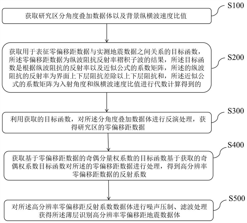
[0054] figure 1 A flow chart of the method for thin layer characterization according to the embodiment of the present invention is schematically shown.

[0055] Such as figure 1 As shown, the method for thin-layer characterization according to the embodiment of the present invention includes the following steps: S100. Acquire the angle-stacked data volume of the research area, and obtain the background P-to-s wave velocity ratio in the study area through pre-stack inversion. S200. Obtain an objective function used to characterize the relationship between the zero-offset data and the measured seismic data, wherein the shift data is a wavelet result of compressional wave impedance reflectivity convolution. The objective function is obtained by algebraic calculation based on the P-wave impedance reflectivity and the coefficient matrix of the approximate formula, where the P-wave impedance reflectivity is the ratio of the impedance difference between the upper and lower layers of...

Embodiment 2

[0080] The method for thin-layer characterization in the embodiment of the present invention preferably further includes step S500 on the basis of embodiment 1: performing noise suppression on the basis of the zero-offset reflection data with improved resolution obtained in step S400 and filtering to obtain zero-offset reflection data with improved longitudinal resolution. On the basis of the obtained zero-offset reflection data with improved resolution, principal component analysis is used to suppress noise, and band-pass filtering is used to suppress abnormal frequency bands to obtain high-resolution zero-offset reflection information. Geological analysis of the target layer and extraction of elastic parameters provide constrained data.

Embodiment 3

[0082] Furthermore, the method for thin-layer characterization in this embodiment of the present invention, on the basis of Embodiment 2, further includes step S600: performing elastic Parameter inversion to analyze the geological evolution of the study area.

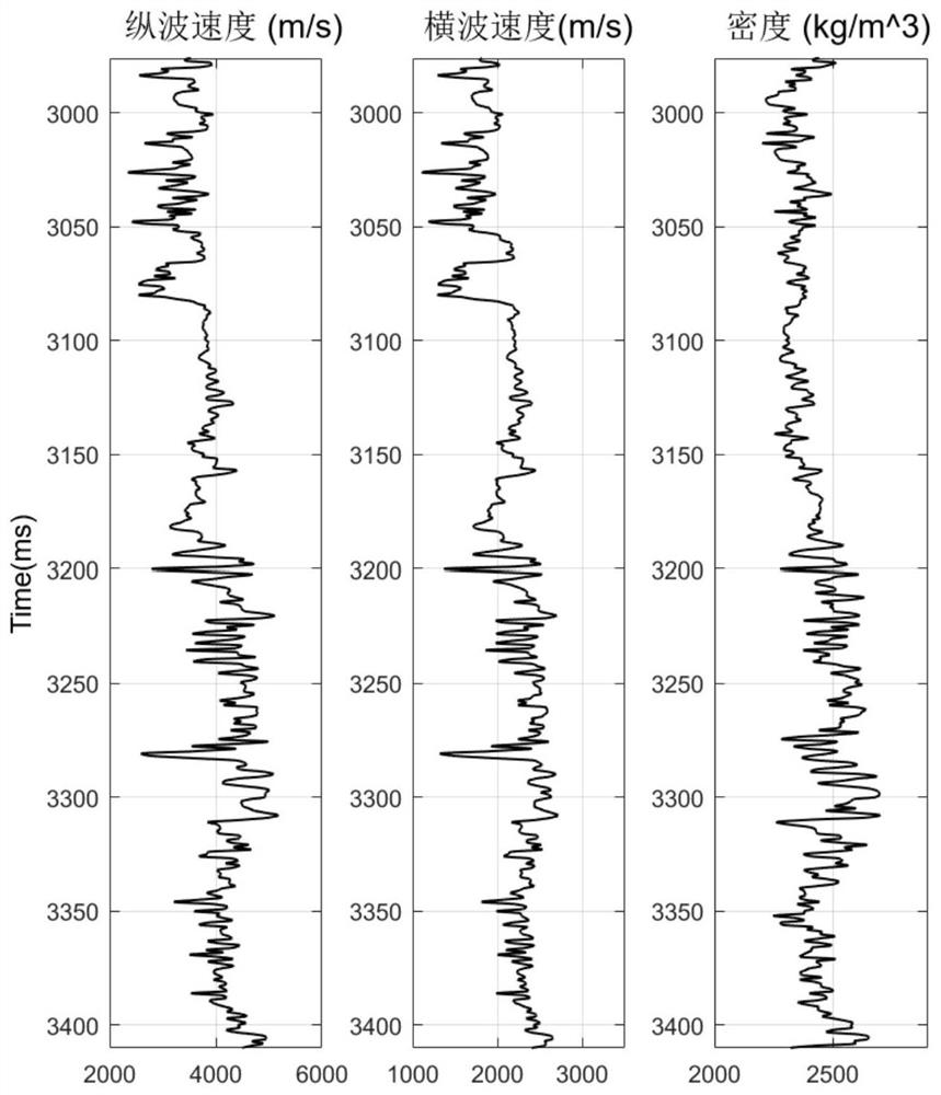
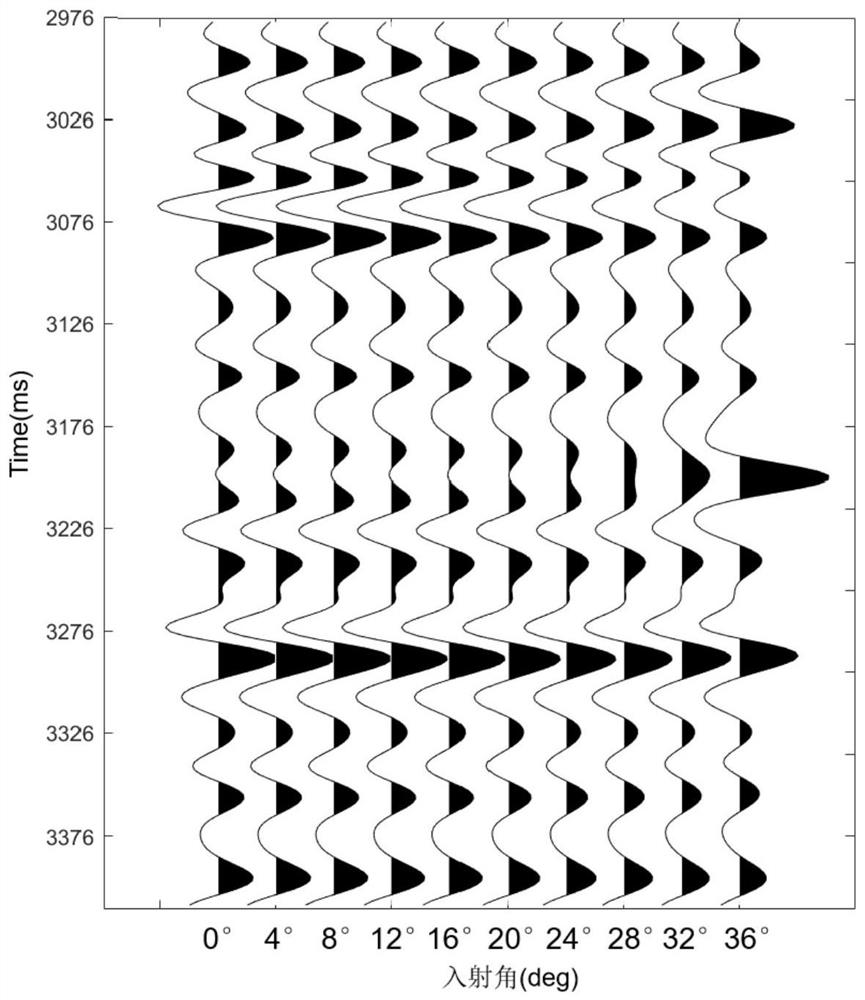
[0083] figure 2 It schematically shows the measured well data of the embodiment of the present invention, including compressional wave velocity, shear wave velocity and density data. Using these three kinds of measured well data, the reflection coefficients at different incident angles are obtained. image 3 Schematically shows the angle gather calculated by using the theoretical logging data. In this embodiment, the incident angle ranges from 0° to 36°, with an interval of 4°, and then the reflection coefficient and the Reich subfolder with a main frequency of 25Hz Gather data from different incident angles can be obtained, and the gather data can be used as observed seismic data.

[0084] Figure 4 Schematically s...


PUM


Abstract

The invention provides a method and system for thin layer depiction, and the method comprises the steps: obtaining a research distinguishing angle superposition data body, and obtaining a background longitudinal and transverse wave speed ratio of a research region through pre-stack inversion; obtaining an objective function used for representing the relation between zero offset data and actually measured seismic data, wherein the offset data is a longitudinal wave impedance reflectivity convolution wavelet result; performing inversion processing on the angle-divided superposition data volume by using the obtained objective function to obtain real zero-offset seismic reflection data of the research area; on the basis of obtaining real zero-offset reflection data obtained based on inversion, obtaining an odd-even component weight coefficient of the zero-offset reflection data, and on the basis, obtaining the zero-offset reflection data after the resolution is improved. According to the method, zero offset information is obtained through a step-by-step method, odd-even component decomposition is carried out on the basis of the zero offset information, the longitudinal resolution of reflection data is improved, and the whole process is more stable compared with multi-angle data superposition direct inversion.

Description

technical field [0001] The present invention relates to the technical field of seismic exploration and processing, in particular to a method and system for thin layer description. Background technique [0002] In conventional processing, in order to improve the signal-to-noise ratio of seismic data, the seismic data acquired by multiple coverage techniques are often superimposed, and the superimposed data is used as the actual self-excited and self-collected data, that is, zero-offset data (Mu Yongguang et al., Seismic Data Processing Methods, 2006). In the face of actual seismic data, the resolution of stacked data is often reduced due to inaccurate dynamic calibration velocity. Even if the dynamic calibration is completely accurate, there are obvious differences in seismic data with different offsets (Z.Sun, Y.Zhang and C.Fan, An iterative AVO inversion workflow for pure P-wave computation and S-wave improvement. The First Break, 2014, 10(32):47-50). The seismic data obt...

Claims


Application Information

Patent Timeline
Patent Type & Authority Applications(China)
IPC IPC(8): G01V1/30G01V1/36
CPCG01V1/302G01V1/307G01V1/36G01V1/306G01V1/303G01V2210/512G01V2210/6222G01V2210/6226G01V2210/6242G01V2210/63
Inventor 马琦琦段太忠廉培庆张文彪赵磊李蒙
Owner CHINA PETROLEUM & CHEM CORP
Why Eureka
Try Eureka