
Head replaceable cutting tool, cutting head, and tool body

A technology of cutting tools and cutting heads, which is applied in the direction of tool workpiece connection, cutting blades, manufacturing tools, etc., can solve the problems of processing accuracy and surface roughness reduction, cutting head shaking, etc., achieve high processing accuracy, prevent shaking, excellent The effect of surface roughness

Pending Publication Date: 2022-02-22
MOLDINO TOOL ENG LTD
View PDF2 Cites 0 Cited by
  • Summary
  • Abstract
  • Description
  • Claims
  • Application Information

AI Technical Summary

Problems solved by technology

Therefore, during cutting, if a large cutting load acts on the cutting edge of the cutting head, the cutting head will shake, which may lead to a decrease in machining accuracy and roughness of the machined surface

Method used


Image

  • Head replaceable cutting tool, cutting head, and tool body
  • Head replaceable cutting tool, cutting head, and tool body
  • Head replaceable cutting tool, cutting head, and tool body

Examples


Embodiment Construction

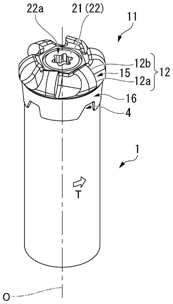
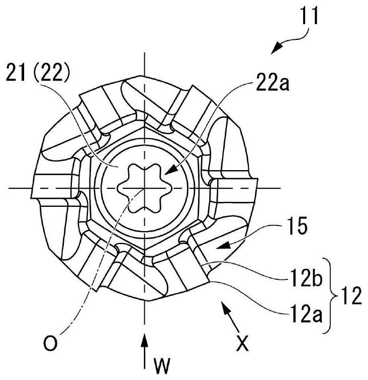
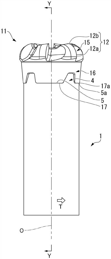
[0049] Figure 1 ~ 11 An embodiment of the head replacement cutting tool of the present invention is shown, Figure 12 ~ 16 One embodiment of the cutting head of the present invention installed in this embodiment is shown. Figure 17 ~ 19 A implementation of a tool body mounted to installing the cutting head is mounted.

[0050] In the present embodiment, the tool body 1 is made of a metal material such as steel such as Figure 17 ~ 19 The cylindrical shaft shape formed in an axis O is shown. In addition, the cutting head 11 is a hard alloy such as a hardness than the hardness of the tool body 1. Figure 12 ~ 16 It is shown in the axis shape as the axis O.

[0051] Such a head replacing the cutting tool, on the basis of the cutting head 11 is mounted on the front end portion of the tool main body 1, the rear end portion of the tool main body 1 is held by the spindle of the machine, while rotating the direction of rotation of the tool around the axis O In the direction of the axis O, t...


PUM


Abstract

This head replaceable cutting tool comprises: a shaft-like tool body (1) which is rotated around an axis line (O) in a tool rotation direction (T); and a cutting head (11) provided with a cutting edge (12) and detachably attached to a front end of the tool body (1). The tool body (1) and the cutting head (11) are attached to each other with a body-side abutting surface (5) on a front end surface of the tool body (1) abutting against and closely attached to a head-side abutting surface (17) on a rear end surface of the cutting head (11). A recess (16) and a protrusion (4) insertable into the recess (16) are formed on the rear end surface of the cutting head (11) and the front end surface of the tool body (1), respectively. The recess (16) and the protrusion (4) are formed to become wider in a circumferential direction toward a radially outer peripheral side with respect to the axis line (O).

Description

Technical field [0001] The present invention relates to a head replacement cutting tool capable of disassembling a cutting edge of a cutting edge in the head replacement cutting tool at the front end portion of a shaft-shaped tool body rotating in the rotation direction of the tool rotation in the tool rotation in the tool. The cutting head that is capable of detachably mounted on the front end, and the cutting head in the head replacement cutting tool can be disassemblely mounted on the front end portion, rotating around the axis along the axis of the tool rotates in the direction of the tool. [0002] The present application requires priority to the provision of Japanese Patent Application No. 2019-147893, requested in Japanese August 2019. Background technique [0003] As such a head replacement cutting tool, for example, in Patent Document 1, the following is described: by holding the mounting screw and setting in the screw insertion hole provided on the axial center of the r...

Claims


Application Information

Patent Timeline
Patent Type & Authority Applications(China)
IPC IPC(8): B23C5/00
CPCB23C5/00B23C2210/02B23C2210/03B23C2210/084B23C2240/24B23C5/16B23C5/10B23B51/00B23B2205/04B23C2210/165
Inventor 稻垣史彦田中总
Owner MOLDINO TOOL ENG LTD
Learn More