
Anti-whiplash mechanism of automobile seat

A car seat, anti-whiplash technology, applied in vehicle seats, special positions of vehicles, vehicle parts, etc., can solve the problems of high manufacturing requirements, high fuel consumption of the whole vehicle, high cost, and achieve low manufacturing requirements, light weight, low cost effect

Pending Publication Date: 2022-02-25
HOZON NEW ENERGY AUTOMOBILE CO LTD
View PDF0 Cites 0 Cited by
  • Summary
  • Abstract
  • Description
  • Claims
  • Application Information

AI Technical Summary

Problems solved by technology

Most of the existing anti-whiplash mechanisms adopt a mechanical structure, which is realized through the adjustment of the seat frame structure. This implementation method has high manufacturing requirements, high cost, and heavy weight, which also leads to high fuel consumption of the vehicle.

Method used


Image

  • Anti-whiplash mechanism of automobile seat
  • Anti-whiplash mechanism of automobile seat

Examples


Embodiment 1

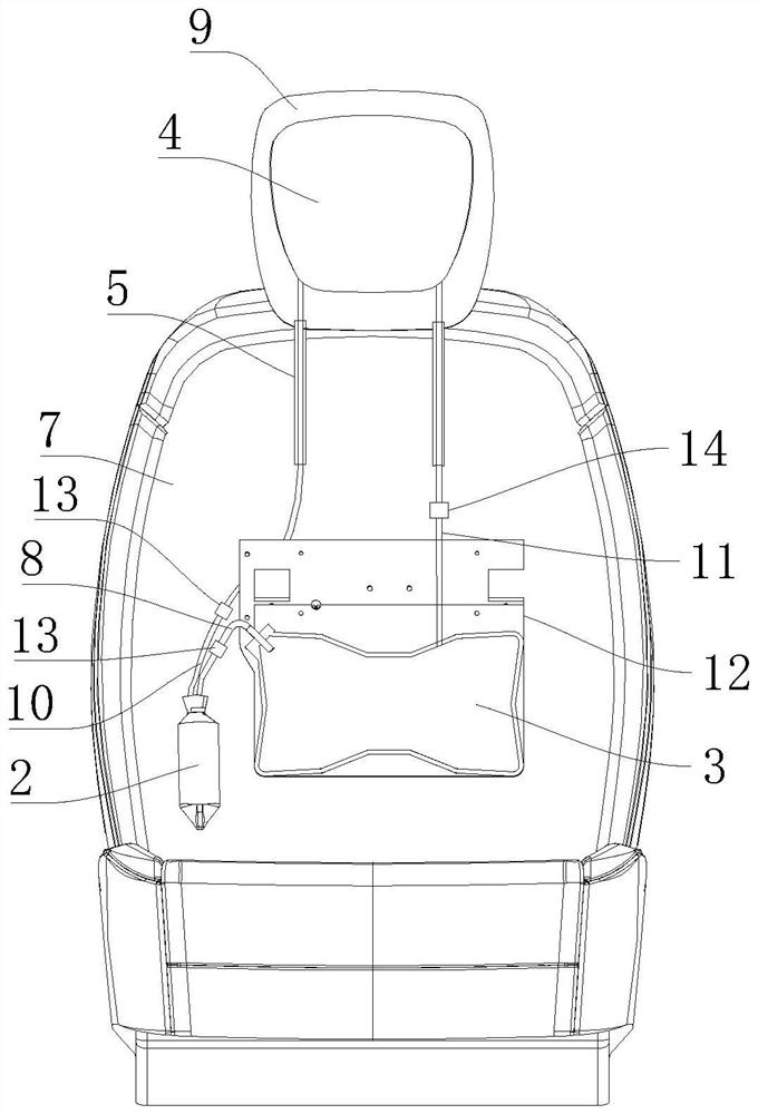
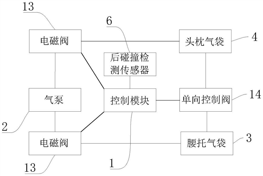
[0018] An anti-whiplash mechanism for a car seat, comprising a control module 1, an air pump 2, a lumbar support air bag 3, a headrest air bag 4, a hollow headrest rod 5 and a rear collision detection sensor 6; the control module 1 is arranged on the vehicle body In the central control large screen, the air pump 2 and the lumbar support air bag 3 are installed in the seat back 7; the air pump 2 and the lumbar support air bag 3 are connected through the first air pipe 8; the headrest air bag 4 Installed in the seat headrest 9; the headrest air bag 4 is connected with the air pump 2 through the second air pipe 10; and the lumbar support air bag 3 and the headrest air bag 4 are passed through the third air pipe 11 connection; two sides of the lower part of the seat headrest 9 are respectively provided with two hollow headrest rods 5; the seat headrest 9 is installed on the seat back 7 through the hollow headrest rods 5 The top of the vehicle; the rear collision detection sensor 6...

Embodiment 2

[0020] An anti-whiplash mechanism for a car seat, comprising a control module 1, an air pump 2, a lumbar support air bag 3, a headrest air bag 4, a hollow headrest rod 5 and a rear collision detection sensor 6; the control module 1 is arranged on the vehicle body In the central control large screen, the air pump 2 and the lumbar support air bag 3 are installed in the seat back 7; the air pump 2 and the lumbar support air bag 3 are connected through the first air pipe 8; the headrest air bag 4 Installed in the seat headrest 9; the headrest air bag 4 is connected with the air pump 2 through the second air pipe 10; and the lumbar support air bag 3 and the headrest air bag 4 are passed through the third air pipe 11 connection; two sides of the lower part of the seat headrest 9 are respectively provided with two hollow headrest rods 5; the seat headrest 9 is installed on the seat back 7 through the hollow headrest rods 5 The top of the vehicle; the rear collision detection sensor 6...


PUM


Abstract

The invention discloses an anti-whiplash mechanism of an automobile seat. The anti-whiplash mechanism comprises a control module, an air pump, a waist support air bag, a headrest air bag, hollow headrest rods and a rear collision detection sensor. The control module is arranged in a vehicle body center control large screen, and the air pump and the waist support air bag are installed in a seat backrest; the air pump is connected with the waist support air bag through a first air pipe; the headrest air bag is mounted in the seat headrest; the headrest air bag is connected with the air pump through a second air pipe; the waist support air bag is connected with the headrest air bag through a third air pipe; two hollow headrest rods are respectively arranged on two sides of the lower part of the seat headrest; the seat headrest is mounted at the top of the seat backrest through the hollow headrest rods; and the rear collision detection sensor is arranged at the tail part of the automobile and is connected with the control module. When rear-end collision happens to the automobile, the headrest air bag is rapidly inflated, the distance between the head and the headrest is reduced, and then the harm of whiplash injury is reduced.

Description

technical field [0001] The invention relates to the technical field of automobile manufacturing, in particular to an anti-whiplash mechanism of an automobile seat. Background technique [0002] With the substantial increase in car ownership, various traffic accidents are also on the rise, especially rear-end collisions. In a rear-end collision, the vehicle in front of the rear-end is subjected to a forward acceleration, and the seat will push the occupant The torso is forward, but the occupant's head will lag due to inertia. This hysteresis makes the occupant's neck tilt back until it reaches the limit, and then the head is accelerated forward by the neck like a whip, which is what causes Whiplash effect of human neck injury. Most of the existing anti-whiplash mechanisms adopt a mechanical structure, which is realized by adjusting the seat frame structure. This kind of realization requires high manufacturing requirements, high cost, and heavy weight, which also leads to hig...

Claims


Application Information

Patent Timeline
IPC IPC(8): B60R21/207B60N2/42B60R21/00B60R21/01
CPCB60R21/207B60N2/42B60R21/00B60R21/01B60R2021/0011B60R2021/0027B60R2021/0048B60R2021/01013B60R2021/2074
Inventor 柴江磊朴喜俊胡磊苏二兰张杨王兴博李宇彤刘业鹏
Owner HOZON NEW ENERGY AUTOMOBILE CO LTD
Learn More