Internal circulation transmission cold batch cylinder and use method thereof

A technology of internal circulation and cold stacking, which is applied to the processing of textile material drums, liquid/gas/steam open fabric processing, and textile material carrier processing, which can solve problems such as poor penetration effects

Pending Publication Date: 2022-02-25
WUHAN TEXTILE UNIV +1
View PDF7 Cites 0 Cited by
  • Summary
  • Abstract
  • Description
  • Claims
  • Application Information

AI Technical Summary

Problems solved by technology

[0007] The purpose of the present invention is to overcome the defects and problems of poor permeation effect in the prior art, and provide a kind of internal circulation drive cold reactor with good permeation effect and its use method

Method used


Image

  • Internal circulation transmission cold batch cylinder and use method thereof
  • Internal circulation transmission cold batch cylinder and use method thereof
  • Internal circulation transmission cold batch cylinder and use method thereof

Examples


Embodiment 1

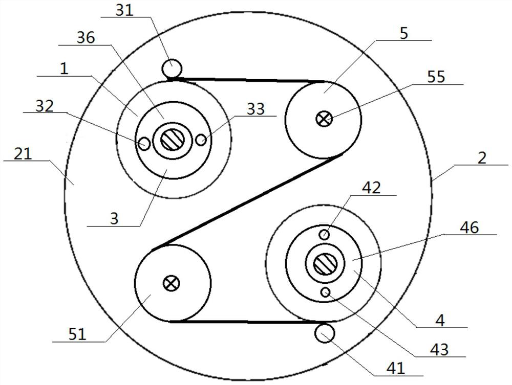
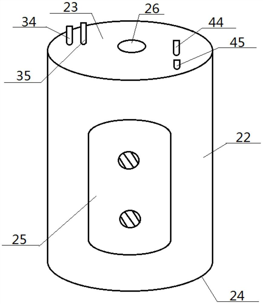
[0056] see figure 1 — Figure 8 , an internal circulating transmission cold stack cylinder, including a liquid-filled cylinder 2 and an inner cylinder cavity 21 provided inside, and the liquid-filled cylinder 2 includes a cylinder side wall 22 and a cylinder top plate 23 and a cylinder bottom plate 24 connected to its two ends , the bottom surface of the cylinder top plate 23 is in contact with the top surface of the cylinder bottom plate 24 through the inner cylinder cavity 21; the first drive roller 3, the second follower roller 5, the third follower roller 51 and the The No. 4 driving roller 4, the No. 1 driving roller 3 and the No. 4 driving roller 4 are respectively located at the two ends of a diagonal line, and the No. 2 follower roller 5 is located on the right side of the No. 1 driving roller 3, so The No. 3 follower roller 51 is located on the left side of the No. 4 drive roller 4; The side circumference of the No. 4 driving roller 4 is driven and matched, and a do...

Embodiment 2

[0059] Basic content is the same as embodiment 1, the difference is:

[0060] A No. 1 fixed roller 31 is arranged on the side of the No. 1 driving roller 3, and the side circumference of the No. 1 fixed roller 31 and the side circumference of the No. 1 driving roller 3 are clamped up and down to carry out transmission cooperation; the No. 4 driving roller The No. 4 fixed roller 41 is arranged on the side of 4, and the side circumference of the No. 4 fixed roller 41 and the side circumference of the No. 4 driving roller 4 are clamped up and down to carry out transmission cooperation; the No. 1 driving roller 3 is located on the No. 1 fixed Between the roller 31 and the No. 3 follower roller 51 , the No. 4 driving roller 4 is located between the No. 4 fixed roller 41 and the No. 2 follower roller 5 .

Embodiment 3

[0062] Basic content is the same as embodiment 1, the difference is:

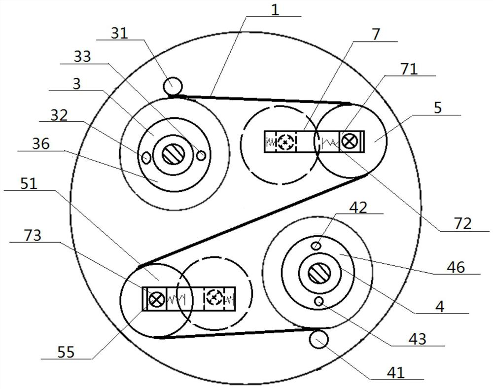
[0063] Structurally: the ends of the No. 2 follower roller 5 and the No. 3 follower roller 51 are set one by one in the roller hole 73, and the roller hole 73 is set in the middle of the roller slider 71. The roller slider 71 is slidingly fitted in the horizontal direction along the inner wall of the roller slider frame 7, the side wall of the roller slider 71 is connected with the inner end of the horizontal spring 72, and the outer end of the horizontal spring 72 faces away from the roller slider 71. Direction extends, and roller slider 71, horizontal spring 72 are all positioned at the inside of roller slider frame 7, and a roller slider 71 corresponds to a roller slider frame 7, and the positions of all roller slider frames 7 are all fixed.

[0064] In terms of method: when the cloth roll 1 drives the No. 2 follower roller 5 and the No. 3 follower roller 51 to rotate together, the side walls of the No. ...


PUM


Abstract

An internal circulation transmission cold batch cylinder comprises a liquid containing cylinder and an inner cylinder cavity formed in the liquid containing cylinder, a first driving roller, a second follow-up roller, a third follow-up roller and a fourth driving roller are arranged in the inner cylinder cavity, the first driving roller and the fourth driving roller are located at the two ends of a diagonal line respectively, the second follow-up roller is located in the right side of the first driving roller, and the third follow-up roller is located in the left side of the fourth driving roller. The side wall of the first driving roller sequentially passes through the side wall of the second follow-up roller and the side wall of the third follow-up roller and then is in transmission fit with the side wall of the fourth driving roller, and the liquid containing cylinder is provided with a bin gate and a liquid inlet which are communicated with the inner cylinder cavity. By means of the design, it can be guaranteed that the front face and the back face of the cloth roll can be permeated, dynamic permeation can be achieved, and the permeation effect is good.

Description

technical field [0001] The invention relates to a pretreatment device for textiles, which belongs to the field of textile equipment, and in particular to an internal circulation transmission cold stacker and a method for using the same. Background technique [0002] At present, the cold pile process is mainly used in the treatment of textiles. The main forms are bleaching first and then stabbing and first stabbing and bleaching. The former has higher breaking strength and elongation, and the latter has better softness and water absorption, but both exist. The problem of high chemical dosage and high energy consumption will cause great pollution to the environment. [0003] In addition, the existing cold stacking process generally involves stacking fabrics or fiber nets in the box and soaking the cold stacking agent, while the commonly used cold stacking boxes are mostly ordinary soaking boxes or cylinders, which not only take a long time to infiltrate, but also It is prone ...

Claims


Application Information

Patent Timeline
Patent Type & Authority Applications(China)
IPC IPC(8): D06B3/32D06B23/20D06B23/02D06B23/04
CPCD06B3/32D06B23/20D06B23/02D06B23/04
Inventor 张如全孙婷李建全邓志祥赵炜孙雷罗霞
Owner WUHAN TEXTILE UNIV
Why Eureka
Try Eureka