Frequency converter control method and device, electronic equipment and storage medium

A frequency converter control and frequency converter technology, which is applied in the direction of controlling electromechanical transmission devices, controlling generators, controlling electromechanical brakes, etc., can solve the problems of serious loss of frequency converter power devices, obvious high-frequency noise of motors, and increased high-frequency noise Achieve the effect of improving vibration and noise problems, facilitating engineering application, and high degree of digitization

Pending Publication Date: 2022-02-25
GUANGDONG MEIZHI COMPRESSOR
View PDF0 Cites 0 Cited by
  • Summary
  • Abstract
  • Description
  • Claims
  • Application Information

AI Technical Summary

Problems solved by technology

However, due to the distortion of the motor air gap magnetic field and the nonlinearity of the IGBT drive module, the motor current contains a large number of high-order harmonics, which can easily cause the motor to heat up, thereby increasing the high-frequency noise
In particular, when the IGBT drive module uses a fixed switching frequency during the entire motor drive process, the high-order harmonics will be concentrated in a fixed frequency range and have a large spectrum peak, resulting in high-frequency noise in a certain speed range of the motor. obvious
In addition, during the operation of the motor, the loss of the power device of the frequency converter is often extremely serious.
[0003] However, there is no effective inverter control method in the related art, which can reduce the loss of inverter power devices while effectively reducing noise.

Method used


Image

  • Frequency converter control method and device, electronic equipment and storage medium
  • Frequency converter control method and device, electronic equipment and storage medium
  • Frequency converter control method and device, electronic equipment and storage medium

Examples


Embodiment Construction

[0048] Embodiments of the present application are described in detail below, and examples of the embodiments are shown in the drawings, wherein the same or similar reference numerals denote the same or similar elements or elements having the same or similar functions throughout. The embodiments described below by referring to the figures are exemplary, and are intended to explain the present application, and should not be construed as limiting the present application.

[0049] The frequency converter control method, device, electronic equipment and storage medium of the embodiments of the present application will be described below with reference to the accompanying drawings.

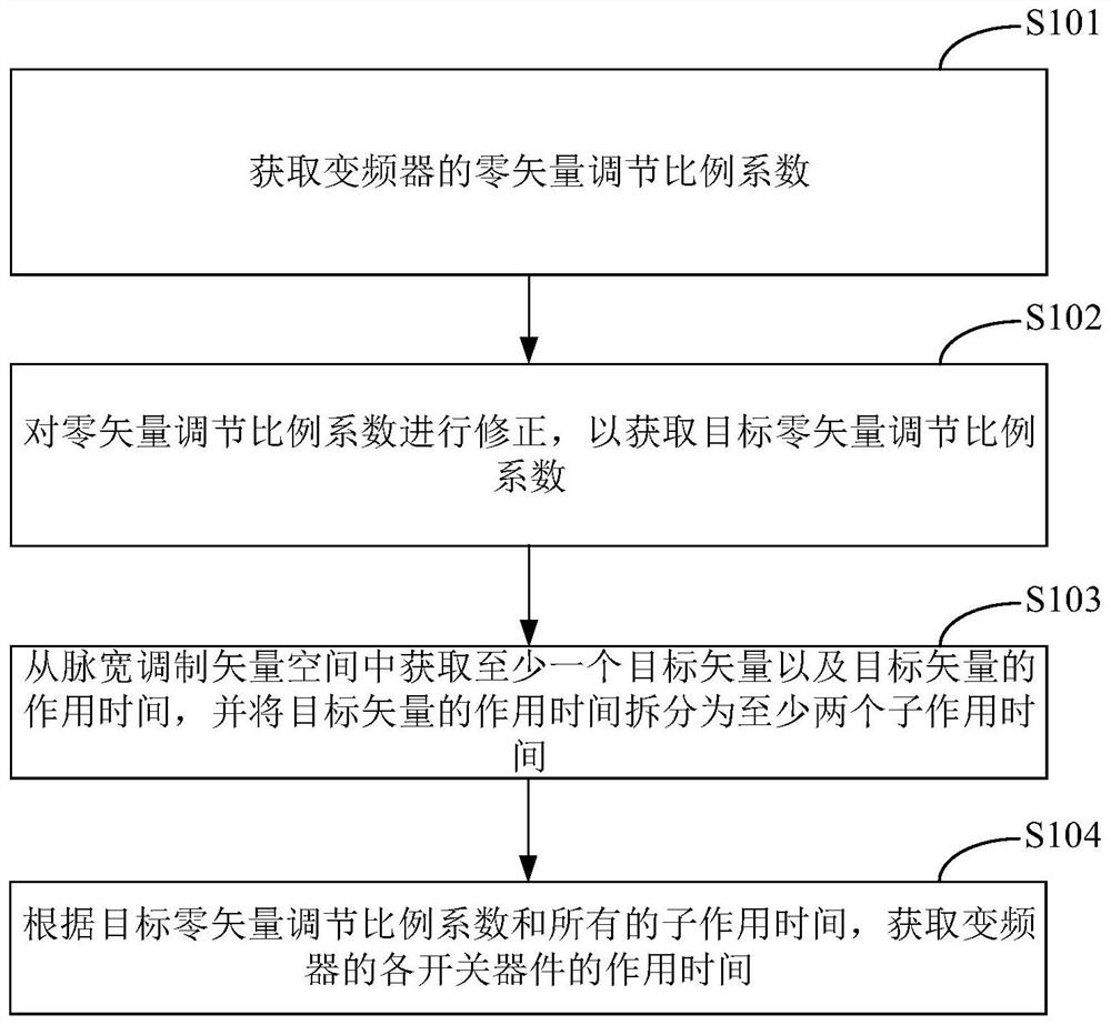
[0050] figure 1 is a schematic flowchart of a method for controlling a frequency converter according to an embodiment of the present application. The inverter control method in the embodiment of the present application can be executed by the inverter control device provided in the embodiment of the pre...


PUM


Abstract

The invention provides a frequency converter control method and device, electronic equipment and a storage medium. The method comprises the steps of: obtaining a zero vector adjustment proportionality coefficient of a frequency converter; correcting the zero vector adjustment proportionality coefficient to obtain a target zero vector adjustment proportionality coefficient; obtaining at least one target vector and action time of the target vector from a pulse width modulation vector space, and splitting the action time of the target vector into at least two sub-action times; and obtaining the action time of each switching device of the frequency converter according to the target zero vector adjustment proportionality coefficient and all the sub-action times. By optimizing a modulation vector sequence, the amplitude of high-frequency current ripples caused by high-frequency carrier waves is remarkably reduced, the problem of vibration noise caused by high-frequency torque pulsation generated by the high-frequency current ripples is solved; and the zero vector adjustment proportionality coefficient is corrected, torque harmonics are optimized, the high-frequency vibration noise of the system is improved, and therefore, the overall performance of the frequency converter is improved.

Description

technical field [0001] The present application relates to the technical field of automatic control, in particular to a frequency converter control method, device, electronic equipment and storage medium. Background technique [0002] At present, permanent magnet synchronous motor (Permanent Magnetic Synchronous Machine, referred to as PMSM) is widely used in various drive control occasions requiring high performance due to its advantages of high efficiency, low vibration and noise, and wide speed range. However, due to the distortion of the motor air gap magnetic field and the nonlinearity of the IGBT drive module, the motor current contains a large number of high-order harmonics, which can easily cause the motor to heat up and increase high-frequency noise. In particular, when the IGBT drive module uses a fixed switching frequency during the entire motor drive process, the high-order harmonics will be concentrated in a fixed frequency range and have a large spectrum peak, r...

Claims


Application Information

Patent Timeline
Patent Type & Authority Applications(China)
IPC IPC(8): H02P27/08H02P21/05H02P21/14
CPCH02P27/08H02P21/05H02P21/14
Inventor 李太龙
Owner GUANGDONG MEIZHI COMPRESSOR
Why Eureka
Try Eureka