Motion shaft positioner for artificial knee joint replacement

An artificial knee joint and motion axis technology, applied in the direction of knee joints, joint implants, joint implants, etc., can solve the problems of too much resection of the tibial lateral condyle, insufficient resection, inconvenient modification of the knee joint surface, etc., and achieve saving The effect of time and money, simple operation and simple structure

Pending Publication Date: 2022-03-01
王志坚
View PDF1 Cites 0 Cited by
  • Summary
  • Abstract
  • Description
  • Claims
  • Application Information

AI Technical Summary

Problems solved by technology

In this case, multiple stylus components are used, and the ends of each stylus component are designed with different thicknesses (such as 1-3mm) to correspond to different articular surface wear and tear due to the loosening of the medial collateral ligament and to stretch the knee joint. It is not actually used to locate the axis of motion; and it is found in clinical practice that if the aforementioned end is against the lateral femoral condyle of the unworn side, and by it Resection of the proximal tibia that provides a reference surface for positioning can easily lead to underresection of the worn medial condyle of the tibia; Too many lateral condyles have been removed, so repeated corrections must be made during the resection process to achieve a balance, which causes inconvenience and trouble in the revision of the knee joint surface

Method used


Image

  • Motion shaft positioner for artificial knee joint replacement
  • Motion shaft positioner for artificial knee joint replacement
  • Motion shaft positioner for artificial knee joint replacement

Examples


Embodiment Construction

[0045] In order to facilitate the explanation of the present invention, the present invention is intended to be expressed in a specific embodiment. Various different objects are depicted in a ratio, size, deformation amount, or displacement amount suitable for explanation, rather than drawing according to the proportion of the actual components, and will be described.

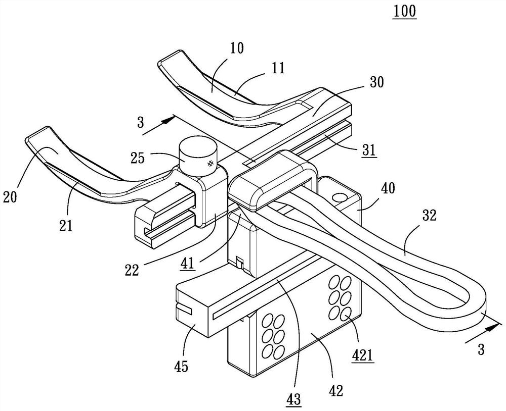
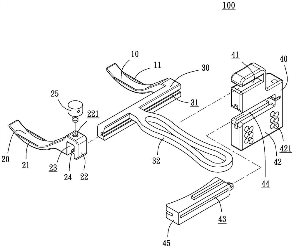
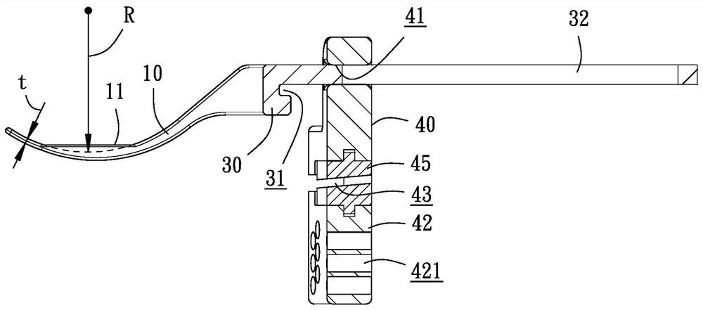
[0046] See Figure 1 to 8 As shown, the present invention provides a motion shaft positioner 100 for artificial knee joint replacement, as the name sustain is used in artificial knee joint replacement, and the definition of this motion axis is clearly described in the background art. Further details will be described again. The motion shaft positioner 100 mainly includes a spoon arm 10, 20 and a joint body, and further includes a guiding cutting member 40 in a preferred embodiment, wherein:

[0047] The spoon arm 10, 20, and the shape are distinguished, respectively, and the curved arc shape described in the scoop i...


PUM


Abstract

The invention provides a motion shaft positioner for artificial knee joint replacement, which comprises two spoon arms and a connecting body, the two spoon arms can be placed between a near-end tibia and a remote femur, and the near-end tibia and the remote femur are restrained by ligaments, so that the inner condyle and the outer condyle of the femur are respectively clamped and propped against the two spoon arms on a tibial plateau at corresponding curvatures; the connecting body naturally positions a reference axis according to the positions where the two spoon arms are clamped and abutted, the reference axis is approximately parallel to the movement axis of relative pivoting of the medial condyle and the lateral condyle on the tibial plateau, and articular surface finishing between the proximal tibia and the remote femur is performed according to the reference axis, so that the device is formed.

Description

Technical field [0001] The present invention relates to an instrument of artificial knee joint replasticization, especially an artificial knee seminotomy. Background technique [0002] Many joints in the human bones, the weight of the knee in the lower extremities, the weight is heavy and frequently fro, so the knee will inevitably cause wear under the use of the month of the year. At this time, the pain is followed, and when the wear is serious, it will result in Incidental action, there is a happening in life, and it is necessary to improve artificial joints through surgery. [0003] Currently, a total of TKNEARTHROPLASTY (TKA), its surgical procedure is to trim the proximaltibial and the distal femurur, then implanted in artificial joints and mats. Among them, since the proximal tibia and remote femoral surgery are removed, it cannot be restored, in order to make the artificial joints can have good adaptability after surgery, how to have a good adaptability in the patient, so ...

Claims


Application Information

Patent Timeline
IPC IPC(8): A61F2/46A61B17/16A61B17/17
CPCA61F2/4657A61F2/461A61B17/1675A61B17/1764A61F2002/4687
Inventor 王志坚
Owner 王志坚
Why Eureka
Try Eureka