Robot motion information planning method and related device

A technology of robot motion and motion information, applied in the direction of manipulators, program-controlled manipulators, manufacturing tools, etc., can solve the problems of not considering time, energy consumption, and the inability to meet the high efficiency and low energy consumption of industrial robots, and achieve the effect of improving the optimization accuracy

Active Publication Date: 2022-03-01
HANGZHOU INNOVATION RES INST OF BEIJING UNIV OF AERONAUTICS & ASTRONAUTICS
View PDF8 Cites 1 Cited by
  • Summary
  • Abstract
  • Description
  • Claims
  • Application Information

AI Technical Summary

Problems solved by technology

[0003]However, the study found that such algorithms do not consider the constraints of time, energy consumption and other factors,

Method used


Image

  • Robot motion information planning method and related device
  • Robot motion information planning method and related device
  • Robot motion information planning method and related device

Examples


Embodiment approach

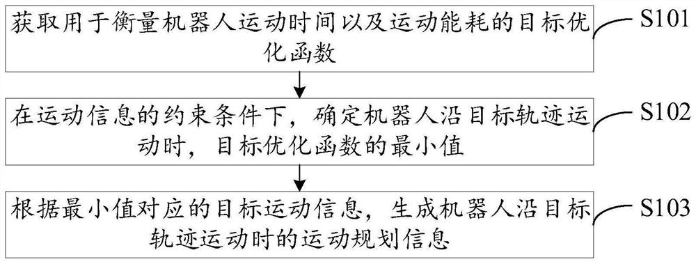
[0048] S103-1. Acquire target motion information corresponding to the minimum value.

[0049] S103-2, performing interpolation processing on the target motion information through a quintic polynomial to obtain motion planning information when the robot moves along the target trajectory.

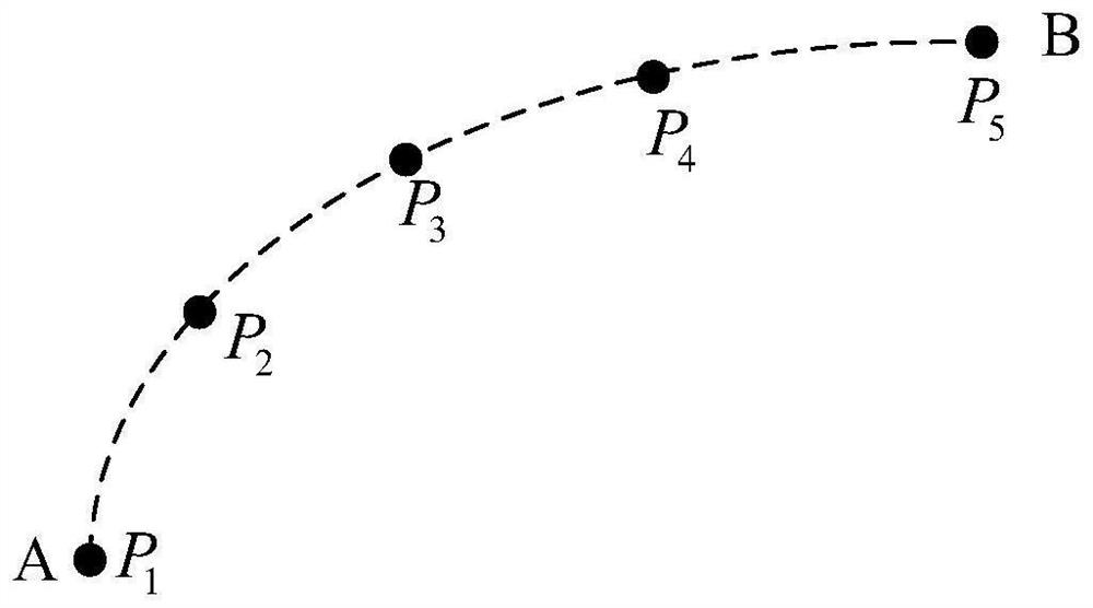
[0050] Exemplary, continue to see image 3 Multiple sampling points in , denoted as P 1 ,P 2 ,P 3 ,P 4 ,P 5 ; For the convenience of description, select P 2 and P 3 Be explained. When the objective optimization function is minimized, it can be solved that the end of the industrial robot is located at P 2 When , the respective angles, rotational speeds and moments of the six joints; and the end at P 3 , the respective angles, rotational speeds and moments of the six joints. Therefore, when the end of the industrial robot moves from P 2 Movement to P 3 During this period, it is necessary to fit the respective angles, rotational speeds and torques of the six joints by means of interp...


PUM


Abstract

According to the robot motion information planning method and the related device provided by the invention, a target kinetic model comprises kinetic parameters of all joints of a robot and friction coefficients of all the joints; a target optimization function used for describing time and energy consumption required when the tail end of the robot moves along a target track is constructed based on the target dynamic model; the target optimization function considers all the joints of the robot and the friction force of each joint, so that the optimization precision of the final time and energy consumption can be improved.

Description

technical field [0001] The present application relates to the field of automatic control, in particular, to a robot motion information planning method and related devices. Background technique [0002] At present, the industry mainly controls the movement of the robot through manual teaching. The trajectory of the robot between multiple teaching points is planned according to the Cartesian space line, arc or spline transition curve. The speed along the path generally adopts polynomial or The spline fitting form solves the robot trajectory with velocity and acceleration constraints. [0003] However, the study found that such algorithms do not consider the constraints of time, energy consumption and other factors, and cannot meet the requirements for high efficiency and low energy consumption of industrial robots in actual industrial scenarios. Contents of the invention [0004] In order to overcome at least one deficiency in the prior art, the present application provides...

Claims


Application Information

Patent Timeline
IPC IPC(8): B25J9/16
CPCB25J9/1664B25J9/1602
Inventor 侯人鸾牛建伟郭昱亮任涛韩冰于晓龙马群
Owner HANGZHOU INNOVATION RES INST OF BEIJING UNIV OF AERONAUTICS & ASTRONAUTICS
Why Eureka
Try Eureka