Kerb mounting trolley

A technology of curbs and trolleys, applied in roads, roads, road repairs, etc., can solve the problems of uneven ground, difficult adjustment and installation of curbs, heavy curb weight, etc., and achieve the effect of good control of the rotation angle

Pending Publication Date: 2022-03-01
GUANGXI ROAD CONSTR ENG GRP CO LTD
View PDF6 Cites 2 Cited by
  • Summary
  • Abstract
  • Description
  • Claims
  • Application Information

AI Technical Summary

Problems solved by technology

[0011] After research, it is found that due to the heavy weight of the curb stone (each curb stone weighs between 100-300kg), and after the curb stone is transported to the installation site, the elevation and axis of the curb stone need to be adjusted repeatedly, so manual work is required However, the ground of the installation environment is sometimes uneven, which leads to the problem that the operator struggles to push the curb installation truck, and it is difficult to adjust and install the curb

Method used


Image

  • Kerb mounting trolley
  • Kerb mounting trolley
  • Kerb mounting trolley

Examples


Embodiment 1

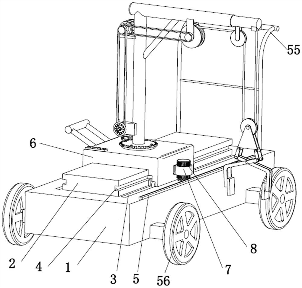
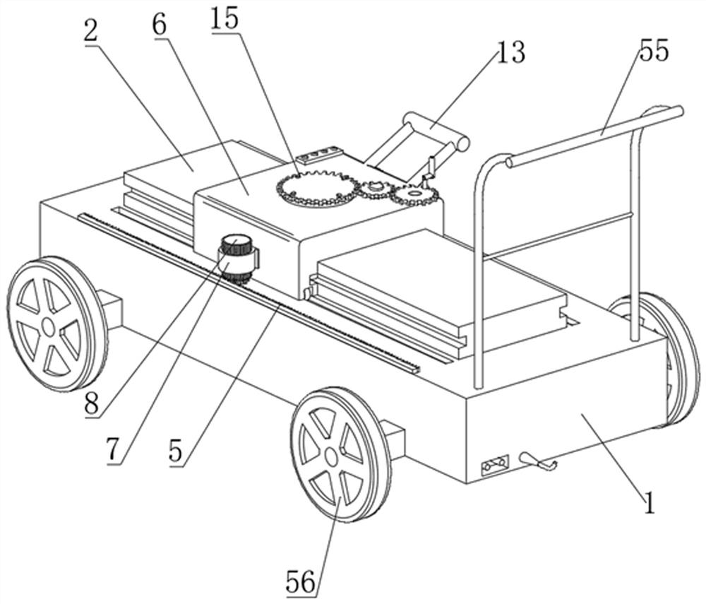
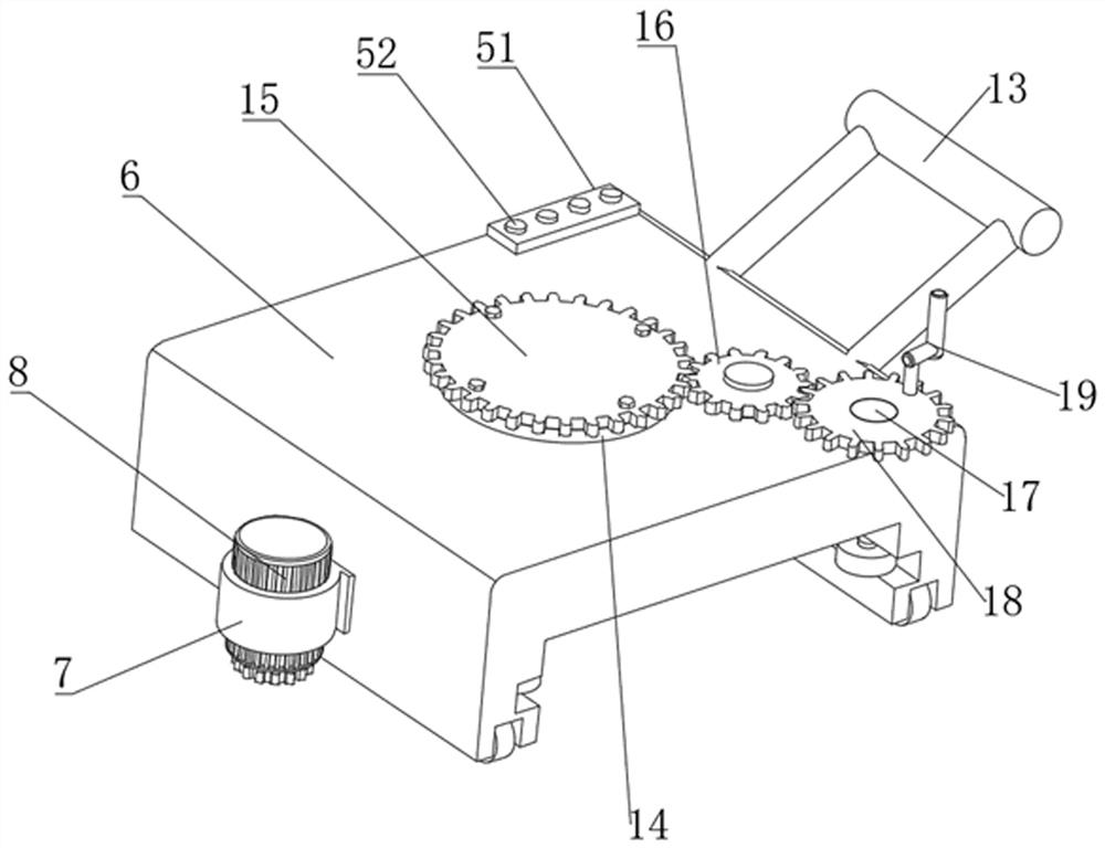
[0044] A trolley for installing curbstones, including a car body 1, wheels 56 are installed on the bottom of the car body 1, a slide rail 2 is arranged on the top of the car body 1, and the top of the car body 1 is along the direction of the slide rail 2 A rack 5 is fixedly arranged, and a moving block 6 is slidably installed on the slide rail 2, and a moving motor 8 is installed on one side of the moving block 6 along the direction of the slide rail 2 through a fixed sleeve 7. The moving A first gear 10 is installed on the rotating shaft 9 of the motor 8, and the first gear 10 meshes with the rack 5; the top of the moving block 6 is rotatably equipped with a first rotating disc 14, and the first rotating disc 14 is fixedly equipped with a second gear 15, the top of the moving block 6 is rotated to install the third gear 16, the third gear 16 meshes with the second gear 15, the top of the moving block 6 is fixedly installed with a fixed rod 17, and the fixed rod 17 is rotatably...

Embodiment 2

[0048]A trolley for installing curbstones, including a car body 1, wheels 56 are installed on the bottom of the car body 1, a slide rail 2 is arranged on the top of the car body 1, and the top of the car body 1 is along the direction of the slide rail 2 A rack 5 is fixedly arranged, and a moving block 6 is slidably installed on the slide rail 2, and a moving motor 8 is installed on one side of the moving block 6 along the direction of the slide rail 2 through a fixed sleeve 7. The moving A first gear 10 is installed on the rotating shaft 9 of the motor 8, and the first gear 10 meshes with the rack 5; the top of the moving block 6 is rotatably equipped with a first rotating disc 14, and the first rotating disc 14 is fixedly equipped with a second gear 15. The top of the moving block 6 is rotated to install the third gear 16, the third gear 16 meshes with the second gear 15, the top of the moving block 6 is fixedly installed with a fixed rod 17, and the fixed rod 17 is rotated an...

Embodiment 3

[0056] A trolley for installing curbstones, including a car body 1, wheels 56 are installed on the bottom of the car body 1, a slide rail 2 is arranged on the top of the car body 1, and the top of the car body 1 is along the direction of the slide rail 2 A rack 5 is fixedly arranged, and a moving block 6 is slidably installed on the slide rail 2, and a moving motor 8 is installed on one side of the moving block 6 along the direction of the slide rail 2 through a fixed sleeve 7. The moving A first gear 10 is installed on the rotating shaft 9 of the motor 8, and the first gear 10 meshes with the rack 5; the top of the moving block 6 is rotatably equipped with a first rotating disc 14, and the first rotating disc 14 is fixedly equipped with a second gear 15. The top of the moving block 6 is rotated to install the third gear 16, the third gear 16 meshes with the second gear 15, the top of the moving block 6 is fixedly installed with a fixed rod 17, and the fixed rod 17 is rotated a...


PUM


Abstract

The invention discloses a kerb installation trolley which comprises a trolley body with wheels installed at the bottom, a sliding rail is arranged at the top of the trolley body, a sliding type moving block is installed on the sliding rail in a sliding mode, and the moving block is driven by a moving motor and a gear and rack moving structure to move on the sliding rail. A first rotating disc is rotatably mounted at the top end of the moving block, a second gear is fixedly mounted on the first rotating disc, a third gear and a fourth gear are rotatably mounted at the top end of the moving block, the fourth gear is meshed with the third gear, the third gear is meshed with the second gear, a fixing rod is fixedly mounted at the top end of the moving block, and a second handle is fixedly mounted on the fourth gear; a hoisting supporting rod is installed at the top of the second gear, a pulley hoisting device which is composed of a fixed pulley and a movable pulley and driven by a lifting motor to wind up a hoisting rope is installed on the hoisting supporting rod, and a gripper used for clamping the curb is installed on the lower portion of the movable pulley. According to the installation trolley, the elevation and the axis of the curb can be easily adjusted.

Description

technical field [0001] The invention relates to the technical field of road construction equipment, in particular to a curb installation trolley. Background technique [0002] At present, with the rapid development of national transportation infrastructure, road construction must be standardized, mechanized and refined. Among them, as roads at all levels and even in the park, there must be a clear dividing line between the roadway and the sidewalk. The dividing line is usually divided by curbstones. The construction of curbstones determines the progress and quality of road construction to a certain extent. [0003] The curb stone refers to the boundary stone set on the edge of the road surface and other structural belts, referred to as the curb stone. The installation and construction of curb stones is an indispensable part of road construction. After the completion of road base construction, curb stones should be installed as soon as possible to ensure that the surface lay...

Claims


Application Information

Patent Timeline
Patent Type & Authority Applications(China)
IPC IPC(8): B66C23/42B66C23/62B66C23/693B66C23/84B66D1/04B66D1/12B66D1/28B66C1/44E01C19/52
CPCB66C23/42B66C23/62B66C23/705B66C23/84B66C1/442B66D1/12B66D1/04B66D1/28E01C19/52
Inventor 张建岭秦成辉董闯龙诚璧张聪陈贵荣韦忠海覃露娜雷雨薇陈群方
Owner GUANGXI ROAD CONSTR ENG GRP CO LTD
Why Eureka
Try Eureka