
Boiler control device and method

A boiler control and combustion chamber technology, applied in the field of boiler control, can solve problems such as small temperature control range, insufficient boiler combustion, single control means, etc., and achieve the effect of avoiding insufficient combustion

Pending Publication Date: 2022-03-01
成都海泰科欣远节能科技有限公司 +1
View PDF0 Cites 0 Cited by
  • Summary
  • Abstract
  • Description
  • Claims
  • Application Information

AI Technical Summary

Problems solved by technology

[0002] At present, the temperature control method of the combustion chamber of the boiler is mainly to control the temperature of the combustion chamber by adjusting the air distribution of the boiler, and the control method is single
[0003] Controlling the temperature of the combustion chamber of the boiler through the boiler air distribution has poor flexibility, serious hysteresis, and difficult precise control, and the temperature control range is small, and the general control range is below 50°C
[0004] There is a problem with the temperature control of the combustion chamber of the boiler. If the temperature is too high, it will often lead to excessive generation of thermal nitrogen oxides, pollute the environment, and cause coking problems in the boiler, threatening the safe production of the boiler; if the temperature is too low, the boiler will not burn properly. Sufficient, a large amount of combustibles are not fully burned and used to be discharged, the boiler efficiency is low, and energy is wasted

Method used


Image

  • Boiler control device and method
  • Boiler control device and method
  • Boiler control device and method

Examples


Embodiment Construction

[0028] The following will clearly and completely describe the technical solutions in the embodiments of the present invention with reference to the accompanying drawings in the embodiments of the present invention. Obviously, the described embodiments are only some, not all, embodiments of the present invention. Based on the embodiments of the present invention, all other embodiments obtained by persons of ordinary skill in the art without making creative efforts belong to the protection scope of the present invention.

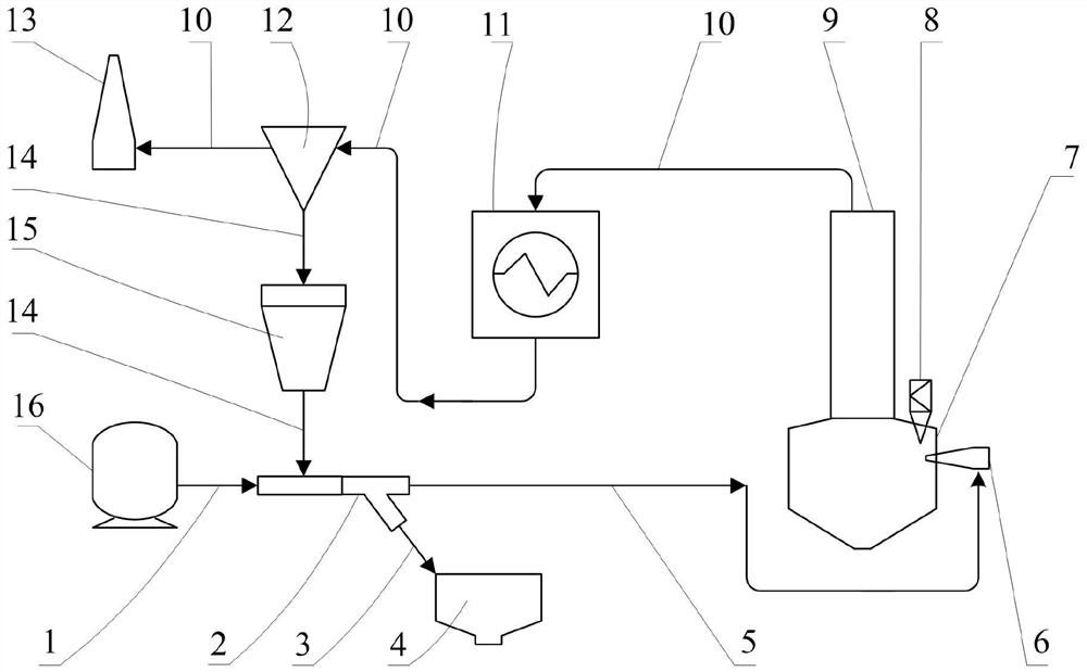
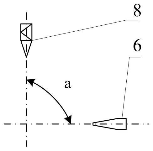
[0029] The embodiment of the invention discloses a boiler control device, such as figure 1 As shown, it includes: ash distributor 2, ash return nozzle 6, combustion chamber 7, burner 8, chimney 13, ash delivery gas source 16 and ash storehouse 4; port a of ash distributor 2 connects with ash delivery gas source pipe 1 The ash gas source 16 is connected, the port b of the ash distributor 2 is connected to the ash storehouse 4, the port c of the ash distributor ...


PUM


Abstract

The invention discloses a boiler control device and method, and relates to the field of boiler control. Fuel characteristics of the boiler and heat exchange characteristics of the hearth are coupled, the temperature of the combustion chamber of the boiler is controlled by adjusting the amount of fly ash fed into the hearth, and the combustion condition of fuel and the generation condition of nitric oxide are further controlled; the problems that the temperature of a combustion chamber deviates from a design value, fuel combustion is insufficient, boiler overtemperature coking is caused, and the generation amount of thermal nitrogen oxides is too high due to design errors, deviation of in-furnace fuel characteristics from the design value, boiler load changes and the like of a traditional boiler are solved. According to the invention, a boiler combustion chamber temperature control means is added, so that the combustion condition of the boiler can be improved, the emission of nitrogen oxides of the boiler can be controlled, the boiler efficiency can be improved, the coking risk of the boiler can be reduced, and the emission of pollutants can be reduced.

Description

technical field [0001] The invention relates to the field of boiler control, and more specifically relates to a boiler control device and method. Background technique [0002] At present, the temperature control method of the combustion chamber of the boiler is mainly to control the temperature of the combustion chamber by adjusting the air distribution of the boiler, and the control method is single. [0003] Controlling the temperature of the combustion chamber of the boiler through boiler air distribution has poor flexibility, serious hysteresis, difficulty in precise control, and a small temperature control range, generally below 50°C. [0004] There is a problem with the temperature control of the combustion chamber of the boiler. If the temperature is too high, it will often lead to excessive generation of thermal nitrogen oxides, pollute the environment, and cause coking problems in the boiler, threatening the safe production of the boiler; if the temperature is too l...

Claims


Application Information

Patent Timeline
Patent Type & Authority Applications(China)
IPC IPC(8): F23N5/00F23C9/08F23J15/02F23J15/06F23L7/00
CPCF23N5/00F23C9/08F23J15/02F23J15/06F23L7/00Y02E20/30
Inventor 王军祥李志伟何秀锦
Owner 成都海泰科欣远节能科技有限公司
Learn More