
Anti-freezing and heat exchange optimized structure of natural ventilation cooling tower of thermal power plant

A technology of natural ventilation and optimized structure, applied in the direction of water shower coolers, heat exchanger types, direct contact heat exchangers, etc., can solve the problems of inability to block side winds, personal injuries, etc., and achieve uniform distribution of aerodynamic field, The effect of enhancing the heat exchange strength

Pending Publication Date: 2022-03-01
SHENYANG INST OF ENG
View PDF0 Cites 0 Cited by
  • Summary
  • Abstract
  • Description
  • Claims
  • Application Information

AI Technical Summary

Problems solved by technology

[0005] For this reason, the present invention provides a natural ventilation cooling tower antifreeze and heat exchange optimization structure of a thermal power plant. The shading area of ​​the sail curtain and the opening angle of the deflector windshield can keep the side wind and keep warm, and the control of the windshield canvas curtain and the deflector windplate can be realized remotely, thus saving human resources and avoiding personal injury Accidents, to solve the problems in the prior art that cannot block the crosswind and easily cause personal injury accidents due to the artificial suspension of the windshield

Method used


Image

  • Anti-freezing and heat exchange optimized structure of natural ventilation cooling tower of thermal power plant
  • Anti-freezing and heat exchange optimized structure of natural ventilation cooling tower of thermal power plant
  • Anti-freezing and heat exchange optimized structure of natural ventilation cooling tower of thermal power plant

Examples


Embodiment Construction

[0032] The implementation mode of the present invention is illustrated by specific specific examples below, and those who are familiar with this technology can easily understand other advantages and effects of the present invention from the contents disclosed in this description. Obviously, the described embodiments are a part of the present invention. , but not all examples. Based on the embodiments of the present invention, all other embodiments obtained by persons of ordinary skill in the art without making creative efforts belong to the protection scope of the present invention.

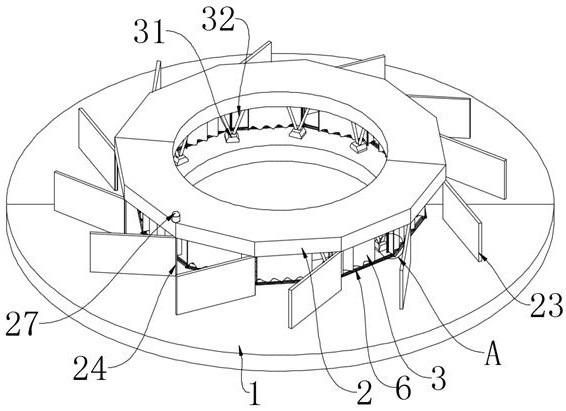
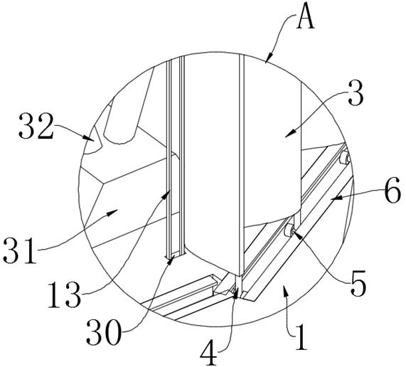
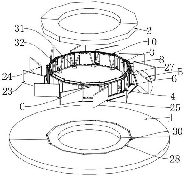
[0033] Refer to the attached Figure 1-4 , 6, 7 and 9-11, a kind of thermal power plant natural draft cooling tower antifreeze and heat exchange optimization structure of this embodiment, comprise two semi-annular bottom plates 1, two semi-annular bottom plates 1 are spliced ​​into a ring, and the two semi-annular bottom plates 1 The top of the semi-annular bottom plate 1 is provided with a semi...


PUM

PropertyMeasurementUnit
Rotation angleaaaaaaaaaa

Abstract

The invention discloses a thermal power plant natural ventilation cooling tower anti-freezing and heat exchange optimized structure, and particularly relates to the technical field of cooling tower anti-freezing, the thermal power plant natural ventilation cooling tower anti-freezing and heat exchange optimized structure comprises two semi-annular bottom plates, the two semi-annular bottom plates are spliced into a ring, and semi-annular top plates are arranged at the tops of the two semi-annular bottom plates; the two semi-annular top plates can be spliced into a ring, a plurality of wind shielding canvas curtains are arranged between the semi-annular top plates and the semi-annular bottom plates, a plurality of vertical rods are fixedly arranged at the tops and the bottoms of the wind shielding canvas curtains, and pulleys are fixedly arranged at the ends, away from the wind shielding canvas curtains, of the vertical rods. The multiple wind shielding canvas curtains and the multiple flow guiding air plates are installed between the semi-annular bottom plate and the semi-annular top plate, crosswind and warm keeping can be achieved by adjusting the shielding area of the wind shielding canvas curtains and the opening angles of the flow guiding air plates, and control over the wind shielding canvas curtains and the flow guiding air plates can be achieved remotely; therefore, manpower resources can be saved, and personal injury accidents are avoided.

Description

technical field [0001] The invention relates to the technical field of cooling tower antifreeze, in particular to an antifreeze and heat exchange optimization structure of a natural ventilation cooling tower of a thermal power plant. Background technique [0002] With the introduction of policies such as energy saving and emission reduction and the restriction of my country's energy structure, hydropower, wind power, nuclear power and photovoltaic power generation and other forms of power generation have developed rapidly, and their installed capacity has increased rapidly. It will be dominated by thermal power generation. [0003] As can be seen from the flow chart of the water circulation system of a thermal power plant, the cooling tower occupies an important position in the entire circulation system. The thermal power plant contains two sets of water circulation systems: one is the working medium water circulation process in the steam-water system: the circulating water ...

Claims


Application Information

Patent Timeline
IPC IPC(8): F28C1/00F28C1/16F28F19/00F28F25/12F28F27/00
CPCF28C1/00F28C1/16F28F19/006F28F25/12F28F27/003
Inventor 潘宏刚赵天宇徐有宁王强姜鑫
Owner SHENYANG INST OF ENG
Learn More