Fuel oil (gas) vertical radiation jet heat pipe heat-blast stove

A heat pipe hot blast stove and heat pipe heat exchanger technology, which is applied to air heaters, fluid heaters, lighting and heating equipment, etc., can solve the problems of flue gas series mixing, tube sheet cracking, and low gas-air heat transfer coefficient. , to achieve the effect of ensuring heat exchange intensity, improving heat exchange intensity and reducing heat transfer thermal resistance

Inactive Publication Date: 2005-11-09
吴江市普天热管技术推广应用研究所
View PDF2 Cites 2 Cited by
  • Summary
  • Abstract
  • Description
  • Claims
  • Application Information

AI Technical Summary

Problems solved by technology

[0002] Existing hot blast stoves for preparing hot air include tubeless sleeve type, shell and tube type and heat pipe type hot blast stoves. The first two are gas-gas convective heat transfer of sensible heat of metal plates and tubes. Due to the low gas-gas heat transfer coefficient , the heat transfer efficiency is low, and the temperature of the furnace wall is high, which affects the service life and safety of the hot blast stove, improves the thermal efficiency, and consumes a lot of metal. At the same time, due to the inconsistent temperature difference and stress, the tube plate cracks and accidents occur when the flue gas is mixed.
[0003] China's patented fuel (gas) heat pipe hot blast stove (patent number: 00202400.4) and fuel (gas) heat pipe hot air heating stove (patent number: 02242161.0) adopt heat pipe vacuum phase change superconducting heat transfer, overcome the defects of the first two kinds of hot blast stoves, The thermal efficiency can reach about 85%, but there is adiabatic combustion in the former large furnace, and the latter furnace flue is set in the air duct and is washed by cross-flow air for convective heat exchange. In both cases, the high-temperature radiation heat energy of the combustion furnace is not utilized enough, and the temperature of the hot air is not very high. The problem

Method used


Image

  • Fuel oil (gas) vertical radiation jet heat pipe heat-blast stove
  • Fuel oil (gas) vertical radiation jet heat pipe heat-blast stove

Examples


Embodiment Construction

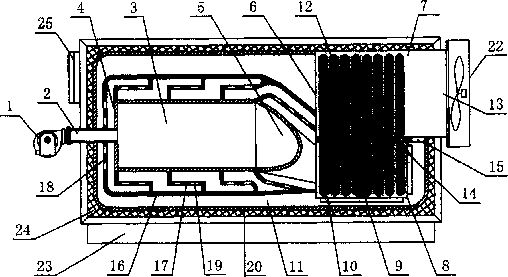
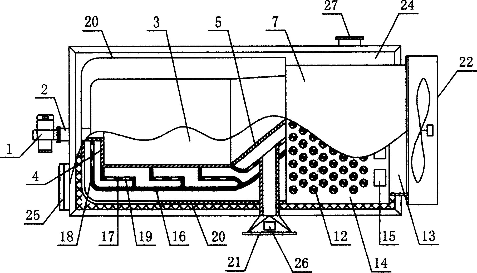
[0015] Referring to Fig. 1 and Fig. 2, the implementation of the present invention mainly includes: burner 1, burner connecting pipe 2, furnace 3, front end cover 4, inclined fire channel 5, heat pipe heat exchanger 6, hot air generating chamber 7, flue 8 , flue partition 9, fins 10, lower air passage 11, heat pipe 12, air inlet and outlet 13, tube plate 14, air inlet 15, air collector 16, spray tube 17, front spray plate 18, spray holes 19, heating Tube 20, hot air outlet 21, fan 22, frame 23, insulation layer 24, automatic control box 25, temperature sensor 26, smoke outlet (27).

[0016] In the implementation of the present invention, the burner connecting pipe (2) is installed on the front end cover (4) of the furnace (3), and the combustion flame of the burner (1) burns in the furnace (3) and enters the flue (8) through the inclined flue (5). ) is formed by a flue partition (9) into a U-shaped flue, which absorbs heat through the heat-absorbing sections of heat pipes (10)...


PUM


Abstract

The invention relates to a fuel oil (gas) verticle radiation jet heat pipe blast stove that is the high temperature radiation jet impact heat exchanger. Reverse fire channels combine the new type high efficiency high temperature hot air indirect heating blast stove. The smoke form the burning firepot would enter into the U shaped smoke channel located at the down side section of the hot pipe heat exchanger from the reverse fire channel, heating the hot pipe heat absorbing section that inserted into the smoke channel. And the working medium would be vaporized after absorbing vaporization latent heat. Vacuum phase changes to the hot pipe fin heat releasing section in the hot air generating room in pipe board. And the air would be fast heated at the intake of fan. The hot air with the temperature of 200-300 degree centigrade would entry into the firepot. And the air would be heated after several times of high temperature radiation. Finally, it would be connected to the hot air application occasion. The heat exchanger intensity would be improved by impacting the outside high temperature surface by high speed air flow. The temperature of hot air could achieve 300-600 degree centigrade. The smoke releasing temperature is below 180 degree centigrade. The heat exchange efficiency would achieve 90%.

Description

Technical field: [0001] The invention relates to a heat source device for preparing hot air, which is widely used in the technological occasions that require hot air heating: wood drying and molding, drying of textile dyeing and finishing industry, rubber vulcanization, polymerization, concentration and evaporation in chemical industry, baking of coating technology Solidification, heating of oil (gas) gathering and transportation coils in oil fields, heating and drying of building materials... Background technique: [0002] Existing hot blast stoves for preparing hot air include tubeless sleeve type, shell and tube type and heat pipe type hot blast stoves. The first two are gas-gas convective heat transfer of sensible heat of metal plates and tubes. Due to the low gas-gas heat transfer coefficient , the heat transfer efficiency is low, and the temperature of the furnace wall is high, which affects the service life and safety of the hot blast stove, improves the thermal effic...

Claims


Application Information

Patent Timeline
Patent Type & Authority Applications(China)
IPC IPC(8): F24H3/06
Inventor 朱友良凌峰
Owner 吴江市普天热管技术推广应用研究所
Why Eureka
Try Eureka