Lamp radiation intensity testing equipment

A technology of radiation intensity and testing equipment, applied in the field of radiation intensity testing equipment of lamps, can solve the problems of inability to observe and remove protective covers, dazzling staff, glare, etc., to avoid excessive carbon dioxide content, avoid light glare, and reduce carbon dioxide content. Effect

Pending Publication Date: 2022-03-01
敦吉电子(上海)有限公司
View PDF0 Cites 2 Cited by
  • Summary
  • Abstract
  • Description
  • Claims
  • Application Information

AI Technical Summary

Problems solved by technology

[0003] In order to check whether the radiation index of the lamps meets the standard, radiation intensity tests are required for the lamps after production. In the prior art, most of the traditional radiation testing devices are hand-held. When using them, the staff need to hold the test device close to the lamps. It will cause certain damage. At the same time, the light of some lamps is relatively strong. During the inspection, the staff need to observe the situation inside the protective cover. However, when the light is strong, the light is still glaring when it passes through the protective cover, which will dazzle the staff and make it impossible to observe. Clear the situation inside the shield

Method used


Image

  • Lamp radiation intensity testing equipment
  • Lamp radiation intensity testing equipment
  • Lamp radiation intensity testing equipment

Examples


Embodiment 1

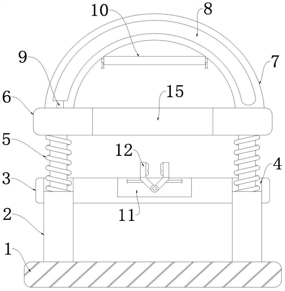
[0021] refer to Figure 1-2 , lamp radiation intensity testing equipment, including a fixed base 1, the upper end of the fixed base 1 is fixedly connected with two symmetrically arranged telescopic rods 2, the telescopic ends of the two telescopic rods 2 are jointly fixedly connected with a movable plate 6, and the upper end of the movable plate 6 Protective cover 7 is installed, is provided with testing device 10 in protective cover 7, and protective cover 7 is made of high-temperature-resistant material, and protective cover 7 is transparent, is convenient for the staff to observe protective cover 7 inner conditions.

[0022] A cavity 8 is provided in the protective cover 7, a fixed plate 3 is arranged above the fixed base 1, and two first through grooves 4 are provided on the fixed plate 3. The inner diameters of the two first through grooves 4 and the diameter of the telescopic rod 2 Similarly, the two telescopic rods 2 pass through the two first through grooves 4 and are ...

Embodiment 2

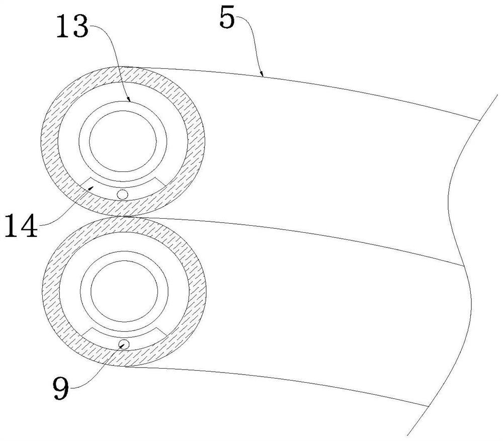
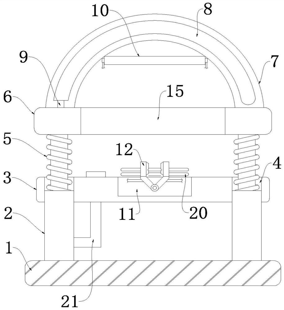
[0030] refer to Figure 3-4 , lamp radiation intensity testing equipment, the telescopic rod 2 is composed of an outer tube 203 and an inner tube 201, the outer wall of one end of the inner tube 201 is bonded to the inner wall of one end of the outer tube 203, the outer tube 203 is provided with a sodium hydroxide solution 16, and the inner tube 201 is provided with a through hole 202, the side wall of the outer tube 203 is provided with a connecting pipe 21, the upper end of the connecting pipe 21 passes through the fixing plate 3 and extends to the upper end surface of the fixing plate 3, the lower end of the inner pipe 201 is connected with the outer An air bag 17 is arranged between the inner bottoms of the tubes 203, and the lower end of the air bag 17 is provided with a one-way liquid inlet pipe 18 and a one-way liquid outlet pipe 19, and a cooling pipe 20 is connected to the one-way liquid outlet pipe 19, and the cooling pipe 20 is ring-shaped Distributed around the ele...


PUM


Abstract

The invention discloses lamp radiation intensity test equipment, which comprises a fixed base, the upper end of the fixed base is fixedly connected with two symmetrically arranged telescopic rods, the telescopic ends of the two telescopic rods are jointly and fixedly connected with a movable plate, the upper end of the movable plate is provided with a protective cover, and the protective cover is internally provided with a test device. A cavity is formed in the protective cover, and a fixing plate is arranged above the fixing base. The device is reasonable in structure, light of the lamp is absorbed by arranging the liquid pumping mechanism, light dazzling is avoided, the situation that a worker observes the state of the lamp is affected, when light is weak, a potassium permanganate solution cannot be pumped into the cavity, the protective cover has good light transmission, a detector clearly observes the internal detection condition, next operation is facilitated, and the working efficiency is improved. By arranging the telescopic rod, the content of carbon dioxide in the protective cover during detection is reduced, and the accuracy of detection data is improved.

Description

technical field [0001] The invention relates to the technical field of radiation detection equipment, in particular to equipment for testing radiation intensity of lamps. Background technique [0002] Radiation refers to the phenomenon that a part of the electromagnetic energy emitted by the field source is separated from the field source and propagated far away, and then no longer returns to the field source. The energy diffuses outward in the form of electromagnetic waves or particles. All objects in nature, as long as the temperature is within When the absolute temperature is above zero, heat is continuously transmitted outward in the form of electromagnetic waves and particles. This way of transmitting energy is called thermal radiation. General lamps will emit radiation of a certain intensity to the outside. When the radiation intensity is high. [0003] In order to check whether the radiation index of the lamps meets the standard, radiation intensity tests are require...

Claims


Application Information

Patent Timeline
Patent Type & Authority Applications(China)
IPC IPC(8): G01J1/02G01J1/04
CPCG01J1/02G01J1/04
Inventor 郭国平郁奇雷
Owner 敦吉电子(上海)有限公司
Why Eureka
Try Eureka