
Turbine blade fatigue test clamp and device

A technology for fatigue testing and turbine blades, which is applied in the field of turbine blades, can solve problems affecting test progress and insufficient pressing force, and achieve the effects of overcoming low vibration energy transfer efficiency, ease of use and operation, and high vibration energy transfer efficiency

Pending Publication Date: 2022-03-01
AECC HUNAN AVIATION POWERPLANT RES INST
View PDF0 Cites 0 Cited by
  • Summary
  • Abstract
  • Description
  • Claims
  • Application Information

AI Technical Summary

Problems solved by technology

However, the existing device has insufficient pressing force, and there is a slight movement between the tenon of the blade and the tenon and groove of the fixture after long-term vibration, which affects the progress of the test.

Method used


Image

  • Turbine blade fatigue test clamp and device
  • Turbine blade fatigue test clamp and device
  • Turbine blade fatigue test clamp and device

Examples


Embodiment Construction

[0026] In order to make the purpose, technical solutions and advantages of the embodiments of the present invention more clear, the technical solutions in the embodiments of the present invention will be clearly and completely described below in conjunction with the accompanying drawings in the embodiments of the present invention. Obviously, the described embodiments It is a part of embodiments of the present invention, but not all embodiments. Based on the embodiments of the present invention, all other embodiments obtained by persons of ordinary skill in the art without making creative efforts belong to the protection scope of the present invention.

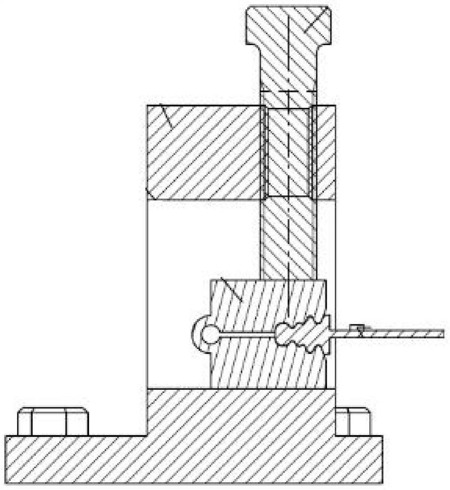
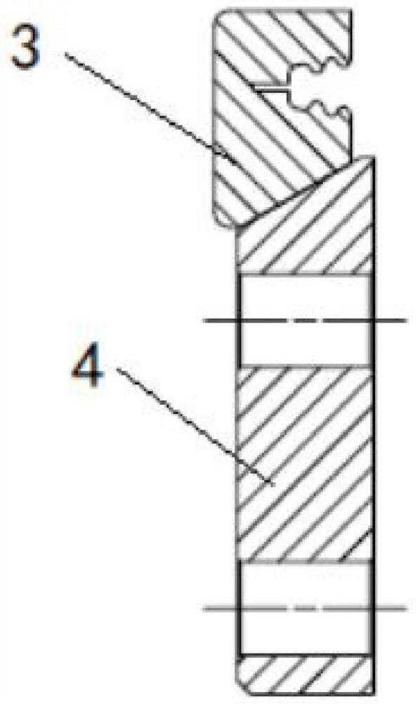
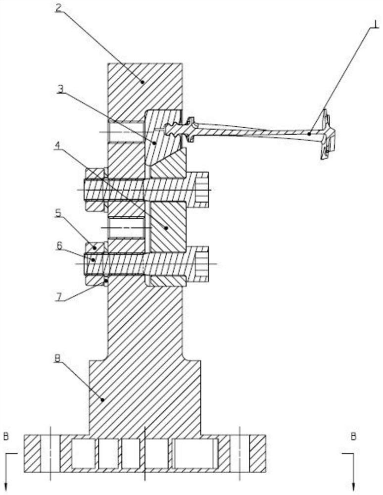
[0027] A turbine blade fatigue test fixture, such as figure 2 As shown, including an upper clamp 3 and a lower clamp 4, the upper end surface of the upper clamp 3 is a horizontal plane, the lower end surface of the lower clamp 4 is a horizontal plane, and the lower end surface of the upper clamp 3 and the upper end surface of...


PUM


Abstract

The invention provides a turbine blade fatigue test clamp and a turbine blade fatigue test device comprising the clamp, the clamp comprises an upper clamp and a lower clamp, the lower end face of the upper clamp and the upper end face of the lower clamp are inclined structures matched with each other, one side face of the upper clamp is provided with a mortise, and the lower end face of the upper clamp is provided with a groove. The inclined structure inclines downwards in the direction from outside to inside along the mortise. The device comprises the clamp, a mounting seat and a vibration table, the bottom of the mounting seat is fixedly arranged on the vibration table, a groove matched with the clamp is formed in the side face of the mounting seat, and the clamp is fixedly arranged in the groove. According to the invention, the clamping mode of the turbine blade is changed, so that the turbine blade is tightly clamped and does not slightly move after long-time vibration, the energy transmission rate of the vibration table is improved, and the test efficiency is improved; the clamp is simple in structure, easy to manufacture and popularize and low in cost; the device and the clamp are simple in structure, easy to install and convenient to use and operate.

Description

technical field [0001] The invention belongs to the technical field of turbine blades, in particular to a fixture and device for a turbine blade fatigue test. Background technique [0002] The turbine blades of modern aero-engines work in high temperature and high pressure environments, and are subjected to the alternating effects of thermal stress, inertial force, aerodynamic force and other forces. The working environment is harsh and the working load is complex, so the turbine blades must meet a certain strength. It can work normally within the safe life cycle. Therefore, it is necessary to test the high temperature fatigue characteristics of turbine blades by means of experiments. [0003] Aeroengine turbine blade fatigue test can obtain the S-N curve of the blade or the fatigue life under the specified load, and the working environment of the blade should be simulated as much as possible to make the test results closer to the real situation. Commonly used test devices...

Claims


Application Information

Patent Timeline
Patent Type & Authority Applications(China)
IPC IPC(8): G01M7/02
CPCG01M7/027
Inventor 彭春雷张萍雷沫枝唐广侯明
Owner AECC HUNAN AVIATION POWERPLANT RES INST
Learn More