Controllable shock wave testing device

A test device and shock wave technology, which is applied in the direction of shock test, measuring device, machine/structural component test, etc., can solve the problems that the shock wave action time cannot be adjusted, the broken diaphragm interferes with the experimental flow field, and the shock wave pressure control is inconvenient. Achieve the effects of saving labor hours, speeding up the test progress, and simple structure

Pending Publication Date: 2022-03-01
上海震业环境科技有限公司
View PDF0 Cites 3 Cited by
  • Summary
  • Abstract
  • Description
  • Claims
  • Application Information

AI Technical Summary

Problems solved by technology

[0004] At present, most of the test devices for generating shock waves basically use bursting discs to explode to generate shock waves, but the broken diaphragm of this type of shock wave instantaneous pressure relief device will interfere with the experimental flow field, and the bursting discs need to be replaced frequently, resulting in low experimental efficiency. Moreover, this type of experimental device cannot adjust the action time of the shock wave, and it is also very inconvenient to control the shock wave pressure.

Method used


Image

  • Controllable shock wave testing device
  • Controllable shock wave testing device

Examples


no. 1 example

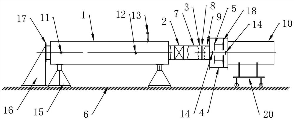
[0024] figure 1 A general structure diagram of the first embodiment of a test device of a controllable shock wave according to the present invention, such as figure 1 As shown, a test device of a controllable shock wave is shown, including a gas storage tank 1 sequentially connected, a quick-opening valve 2, a buffer assembly 3, and a mounting tank 4, which is provided on the gas storage tank 1. The air valve 11 and the pressure relief valve 12 are mounted in the mounting tank 4, and the gas storage tank 1 is provided with at least one pressure sensor 13, and the mounting tank 4 is located at both ends of the test member 5, and at least one shock wave sensor. 14.

[0025] Further, as a preferred embodiment, the buffer assembly 3 includes a transition tube 7 sequentially connected, at least one restricted flow plate 8 and a buffer tube 9, a transition tube 7 and a fast-opening valve 2 connection, buffer tube 9 and the mounting tank 4 connect.

[0026] Further, as a preferred embod...

Embodiment approach

[0029] In a further embodiment of the invention, please continue to see Figure 1 to 2 As shown, the current limiting plate 8 is a hole plate. Preferably, the current limiting plate 8 is a current limiting plate 8 that can be configured as needed as needed.

[0030] In a further embodiment of the present invention, the test device of the controllable shock waves further includes: a wind tube 10, a wind tube 10 is connected to the mounting tank 4, and the wind tube 10 is inserted with the buffer tube 9.

[0031] In a further embodiment of the invention, the gas storage tank 1, the transition tube 7, and the buffer tube 9 are coaxial.

[0032] Preferably, the intake valve 11 and the pressure relief valve 12 are located on the side wall of the gas storage tank 1.

[0033] In a further embodiment of the present invention, a fixed base 15 is provided at the bottom of the gas storage tank 1, and the gas storage tank 1 is provided with a buffer seat 16, and the buffer seat 16 is provided ...

no. 2 example

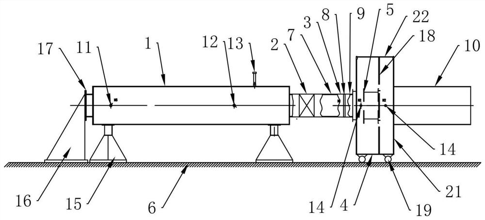
[0053] Such as figure 2 Distance figure 2 A general structure diagram of a second embodiment of a test device of a controllable shock wave according to the present invention, the main structure of the present embodiment is substantially identical to the first embodiment, and is different in that the movable support device is a plurality of roller 19.

[0054] Preferably, the mounting tank 4 includes a tank 21 and a can cover 22, which can be mounted on the mounting frame 18 by opening the can cover 22.

[0055] Preferably, the roller 19 is provided at the bottom of the mounting tank 4.

[0056] The mounting tank 4 of the present embodiment includes: the can body 21 and the can cover 22, and the mounting frame 18 and the bottom arrangement roller 19 are disposed. When the test piece 5 is installed, the mounting tank 22 is opened, and then the test member 5 from the mounting tank 4 The top is lifted, the operator mounts the test member 5 into the mounting frame 18 in the can body 21...


PUM


Abstract

A controllable shock wave test device disclosed by the present invention comprises a gas storage tank, a quick-opening valve, a buffer assembly and an installation tank which are connected in sequence, the buffer assembly comprises a transition pipe, at least one flow limiting plate and a buffer pipe which are connected in sequence, the gas storage tank is provided with a gas inlet valve and a pressure relief valve, a test piece is installed in the installation tank, the gas storage tank is provided with at least one pressure sensor, and the pressure sensor is connected with the gas storage tank. And at least one shock wave sensor is arranged at each of two ends of the test piece in the mounting tank. The device is simple in structure and high in experiment efficiency, the action duration of shock waves can be adjusted according to test requirements, the device is completely different from a traditional TNT explosive shock wave test and a detonation type shock tube test, replacement of a rupture disk is avoided, the test progress is greatly accelerated, for a standard shock wave chamber test room, manpower needed by the test can be reduced by 70% or above, and the test efficiency is improved. The labor hour of a single laboratory is saved by more than 4000 hours per year, and the cost of more than 0.2 billion RMB can be saved for the same type of laboratories in the whole society every year.

Description

Technical field [0001] The present invention relates to the technical field of shock wave test equipment, and more particularly to a test device for controllable shock waves. Background technique [0002] In an occasion of instant release of high and low pressure, there is a shock wave, such as explosion and explosion, there is a shock wave of different pressures. The device currently generating shock waves is a TNT explosive explosion, explosive hoses or high pressure hosted drain discharges. [0003] The shock wave is an important physical phenomenon in the airflow. The impact wave pipe is an experimental device that generates a shock wave, and a shock wave is generated by utilizing a high and low segment. The key to the impact wave pipe design is that the instant relief apparatus has a substantial requirement of its design, and the gas emission flow is large, and the operation is convenient. In the same case of other conditions, the quick slowness of the unforced pressure dire...

Claims


Application Information

Patent Timeline
Patent Type & Authority Applications(China)
IPC IPC(8): G01M7/08
CPCG01M7/08
Inventor 丁宇峰程文平郭世权刘晋许珍斌赵宏刚杨凯
Owner 上海震业环境科技有限公司
Why Eureka
Try Eureka