
Automatic test system and test method for optical transmitter and receiver

An automatic test system and test method technology, applied in the field of optical transceivers, can solve the problem that the optical transceiver cannot be found and illuminated in time, and achieve the effect of improving accuracy and comprehensiveness

Inactive Publication Date: 2022-03-01
保定卓能电力科技有限公司
View PDF0 Cites 0 Cited by
  • Summary
  • Abstract
  • Description
  • Claims
  • Application Information

AI Technical Summary

Problems solved by technology

[0004] Aiming at the deficiencies of the prior art, the present invention provides an automatic test system and testing method for optical transceivers, which solves the existing problem of "the fault indicator light test is relatively simple, and cannot be found and turned on in time when the optical transceiver is not working normally"

Method used


Image

  • Automatic test system and test method for optical transmitter and receiver
  • Automatic test system and test method for optical transmitter and receiver
  • Automatic test system and test method for optical transmitter and receiver

Examples


Embodiment Construction

[0033] Next, the technical solutions in the embodiments of the present invention will be described in connection with the drawings of the embodiments of the present invention, and it is understood that the described embodiments are merely the embodiments of the present invention, not all of the embodiments. Based on the embodiments of the present invention, all other embodiments obtained by those of ordinary skill in the art are in the range of the present invention without making creative labor premise.

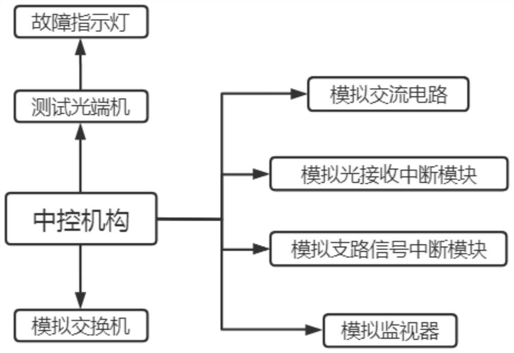
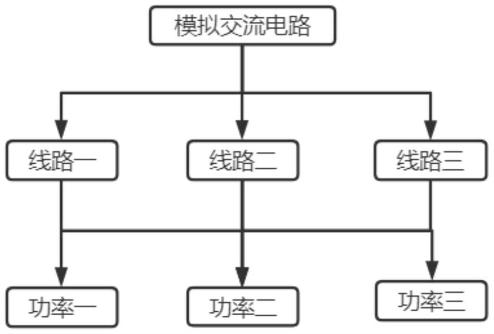
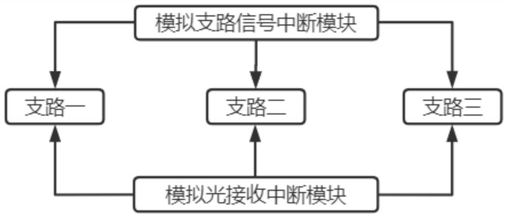
[0034] See Figure 1-3 In this embodiment: an optical automatic test system, a central control mechanism, a test optical terminal body, a fault indicator, analog switch, analog AC circuit, analog light receiving interrupt module, analog branch signal interrupt module, analog monitor;

[0035] Central Control Mechanism: Used to control the normal operation of the optic endor body and the analog switch, provide the normal operation of the test;

[0036] Test Optical Machine Main Bo...


PUM


Abstract

The invention belongs to the technical field of optical transceivers, and particularly relates to an automatic test system for an optical transceiver, which comprises a central control mechanism, a test optical transceiver main body, a fault indicating lamp, an analog switch, an analog alternating current circuit, an analog optical receiving interruption module, an analog branch signal interruption module and an analog monitor. The central control mechanism is used for controlling the normal operation of the test optical transmitter and receiver main body and the analog switch and providing guarantee for the normal operation of the test; and the to-be-detected optical transmitter and receiver is electrically connected with the central control mechanism and the analog switch. According to the automatic test system and test method for the optical transmitter and receiver, by arranging the analog alternating current circuit, the number of lines in the analog alternating current circuit and the power transmission value of the lines can be adjusted, and according to the adjustment test of the number of the lines and the power transmission value, the operation states of the fault indicator lamp under different degrees of signal interference can be tested; and the accuracy and comprehensiveness of the test are improved.

Description

Technical field [0001] The present invention relates to the field of optical terminal technology, and is specifically an optical automatic test system and a test method. Background technique [0002] The optical terminal is the terminal device transmitted by the optical signal. Due to the current improvement of technology, the decrease in fiber prices has made it a good application in various fields, which is mainly reflected in security monitoring, so the manufacturers of various optical terminals are like the spring bamboo shoots, but most of the manufacturers here are not Completely mature, developing new technologies requires cost-consumption and manpower, material resources, etc. These manufacturers are mostly small and medium-sized enterprises, and each brand has also emerged. [0003] The fault indicator is placed in the optical terminal. When the optical terminal is faulty or not working properly, the fault indicator will illuminate, but the current fault indicator is mor...

Claims


Application Information

Patent Timeline
Patent Type & Authority Applications(China)
IPC IPC(8): H04N7/22
CPCH04N7/22
Inventor 王益忠党焕珍王绍琪
Owner 保定卓能电力科技有限公司
Learn More