Surgical instrument protection and storage device for plastic surgery
A storage device and appliance technology, applied in the fields of surgery, medical science, surgical equipment, etc., can solve the problems of inaccurate manual counting of surgical instruments, exposure of instruments to the air, prone to errors, etc., so as to shorten the opening time, ensure storage, and facilitate the stored effect
- Summary
- Abstract
- Description
- Claims
- Application Information
AI Technical Summary
Problems solved by technology
Method used
Image
Examples
Embodiment 1
[0044] The existing disinfection and storage equipment for medical general surgery instruments is mainly composed of inner and outer boxes, display racks, controllers, and ultraviolet lamps. The box door is used for storage, but because the internal space of the box body is connected, when the box door is opened to take out the surgical instruments, all the surgical instruments inside the box body will be exposed to the air, which is not conducive to the disinfection and preservation of surgical cuts. It is easy to be polluted; when accessing surgical instruments, the number of surgical instruments is manually counted, which is prone to errors or omissions, resulting in inaccurate counting, inconvenient management of surgical instruments, and increased workload of personnel.
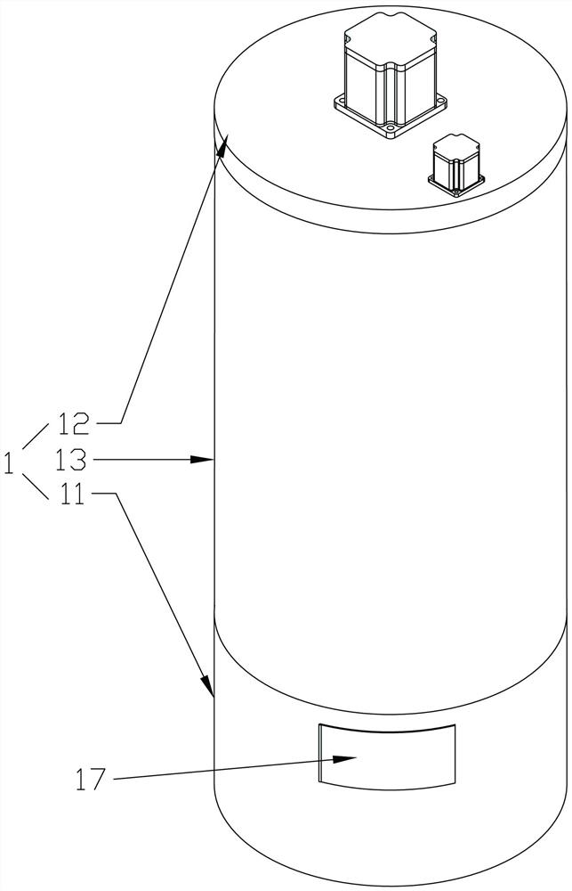
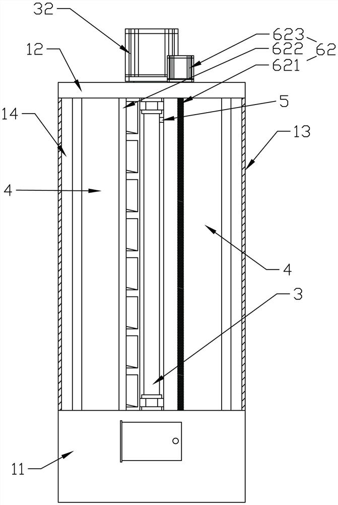
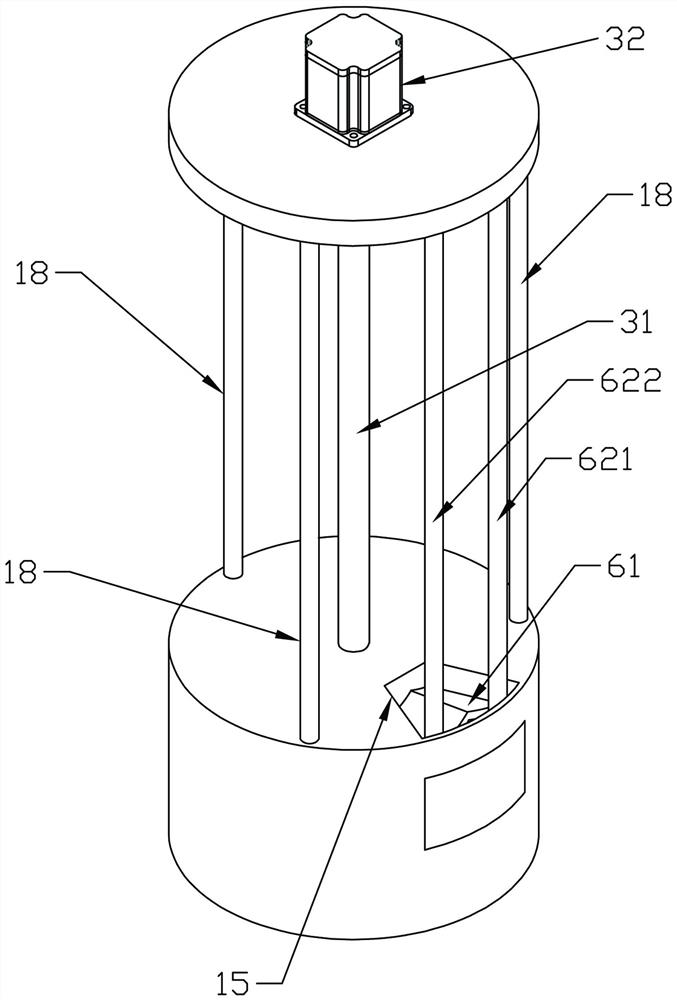
[0045] In view of the above problems, this embodiment provides a protective storage device for surgical instruments used in plastic surgery, such as Figure 1-16 As shown, it includes a placement rack, a...
Embodiment 2
[0066] The difference between embodiment 2 and embodiment 1 is that the structures of the grasping components are different.
[0067] Such as Figure 18 As shown, the bottom of the opening of each storage chamber 42 is vertically provided with a relief groove 44, and the bottom of each appliance box 2 corresponding to the opening of the storage chamber is provided with a hook groove 21 upwards. After the box is placed in the storage room, the hook groove 21 of the utensil box is located above the area of the trough; if Figure 19 As shown, the grabbing part includes a hook rod, and the hook rod includes a vertical rod. The right side wall of the push rod goes up to the receiving groove 6321, and the receiving groove penetrates upward through the push rod. One end of the vertical rod 6334 is hingedly installed through a pin shaft 6335. Inside the storage tank, and the pin shaft is provided with a torsion spring, the torsion spring will drive the connecting section of the hoo...
Embodiment 3
[0070] The difference between embodiment 3 and embodiment 2 is that, as figure 2 and Figure 10 As shown, three support rods 18 are evenly spaced along the circumference in the seal placement chamber between the annular seal cover 13 and the rotating storage cabinet, and one end of the support rod 18 is vertically fixed to the base, and the other end is vertically fixed to the bottom surface of the top plate. Together, they are used to support the top plate 12, reduce the pressure on the annular sealing cover, improve the structural strength and stability of the support, and prolong the service life of the shelf.
PUM
 Abstract
Description
Claims
Application Information
 - R&D
- Intellectual Property
- Life Sciences
- Materials
- Tech Scout
- Unparalleled Data Quality
- Higher Quality Content
- 60% Fewer Hallucinations
Browse by: Latest US Patents, China's latest patents, Technical Efficacy Thesaurus, Application Domain, Technology Topic, Popular Technical Reports.
© 2025 PatSnap. All rights reserved.Legal|Privacy policy|Modern Slavery Act Transparency Statement|Sitemap|About US| Contact US: help@patsnap.com


