Supercharge Your Innovation With Domain-Expert AI Agents!

Cutter

A cutting tool and blade technology, which is applied in the field of end face groove processing at the bottom of the deep hole cavity, can solve the problems of insufficient rigidity, tool vibration, tool chipping, etc., and achieve the effects of enhancing stability, improving processing efficiency, and ensuring processing quality

Active Publication Date: 2022-03-04
XIAN SPACE ENGINE CO LTD
View PDF6 Cites 0 Cited by
  • Summary
  • Abstract
  • Description
  • Claims
  • Application Information

AI Technical Summary

Problems solved by technology

[0003] This kind of slender tool holder with a circular cross section generally has insufficient rigidity, and it is prone to tool vibration caused by insufficient rigidity, which will cause tool chipping, poor surface finish of the workpiece, and insufficient dimensional accuracy.

Method used


Image

  • Cutter
  • Cutter
  • Cutter

Examples


Embodiment Construction

[0028] The present invention will be described in detail below based on specific embodiments and with reference to the accompanying drawings. It should be understood that the specific embodiments described here are only used to explain the present invention, not to limit the present invention.

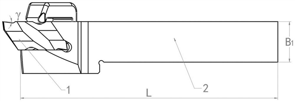
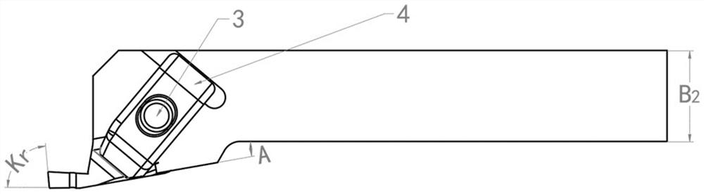
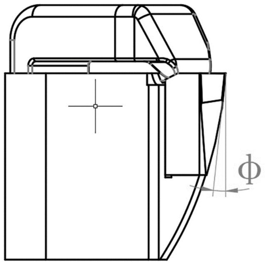
[0029] figure 1 , figure 2 as well as image 3 are respectively the front view, top view and left view of the tool provided by the embodiment of the present invention, Figure 4 It is a schematic diagram of the structure of the cutter bar of the cutter provided by the embodiment of the present invention. Figure 5 It is an overall isometric view of the installed blade and tool holder provided by the embodiment of the present invention.

[0030] combine Figure 1 to Figure 4 As shown, the tool provided by the embodiment of the present application includes: a blade 1 , a tool holder 2 , a pressing piece 4 , a locking screw 3 and a blade slot 5 . like Figure 4 As shown, the blade...


PUM


Abstract

The invention discloses a cutter. The cutter comprises a blade, a cutter bar, a pressing piece, a locking screw and a blade clamping groove. The blade clamping groove is formed in the cutter bar, the blade is installed on the blade clamping groove, the pressing piece and the locking screw are used for pressing the blade, the cutter bar is connected with a cutter holder on a machine tool spindle, and the cutter holder can stretch out by a first size and stretch into an inner cavity of a deep hole together with the cutter bar; the axial deflection angle A is formed between the outer end face of the blade clamping groove in the cutter bar and the cutter bar, the axial deflection angle A is formed between the outer end face of the blade clamping groove in the cutter bar and the cutter bar, and the cutter bar and the hole wall can be effectively avoided through the included angle between the outer end face of the blade and the axial direction. The defects that a conventional square cutter bar interferes with a hole wall and a circular cutter bar is poor in rigidity can be overcome, the stability of a cutter system can be enhanced, the machining quality can be guaranteed, and the machining efficiency is improved.

Description

technical field [0001] The invention belongs to the technical field of deep hole inner cavity bottom end surface groove processing, and in particular relates to a cutting tool. Background technique [0002] At present, for the machining of the end face grooves at the bottom of the deep hole inner cavity of difficult-to-machine materials such as high-temperature alloys, most of the tool holders with a circular cross section are used. In the case of the wall, the end face groove is machined. [0003] This kind of slender tool holder with a circular cross-section is generally insufficient in rigidity, and it is prone to tool vibration caused by insufficient rigidity, resulting in tool chipping, poor surface finish of the workpiece, and insufficient dimensional accuracy. In addition, since the workpiece material is a high-temperature alloy, which is a difficult-to-machine material, and the end groove is located at the bottom of the deep hole cavity, the selection of the main cu...

Claims


Application Information

Patent Timeline
IPC IPC(8): B23B27/16
CPCB23B27/16
Inventor 葛宝李波李亮崔涛张小飞梁雪利
Owner XIAN SPACE ENGINE CO LTD
Features
  • R&D
  • Intellectual Property
  • Life Sciences
  • Materials
  • Tech Scout
  • Unparalleled Data Quality
  • Higher Quality Content
  • 60% Fewer Hallucinations
Learn More