
Pneumatic hole extrusion device and hole extrusion method thereof

A pneumatic and cylinder technology, applied in the field of pneumatic extrusion device, can solve the problems of high mold opening cost, high production cost and low efficiency, and achieve the effect of simple and convenient extrusion operation, low production cost and high operation efficiency

Pending Publication Date: 2022-03-04
武汉华夏精冲技术有限公司
View PDF0 Cites 0 Cited by
  • Summary
  • Abstract
  • Description
  • Claims
  • Application Information

AI Technical Summary

Problems solved by technology

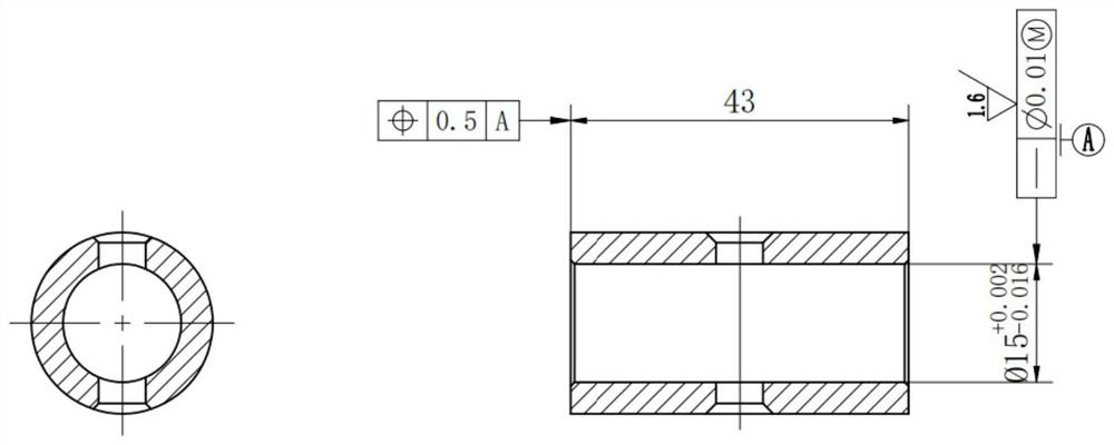
[0002] It is difficult to ensure the machining accuracy of the inner hole of round pipe parts, because it is easy to produce local deformation under the action of external force, especially when the workpiece wall thickness error is large or the clamping force is unevenly distributed, the deformation will be more obvious
In addition, during the cutting process, the heat generated will also cause the workpiece to deform, and the deformation is difficult to control due to the different cutting parameters, tools and workpiece materials.
In addition, when the workpiece is cut, the cutting force acting on the workpiece, especially the radial cutting force, is prone to vibration, which is more obvious for thin-walled workpieces, resulting in deformation of the workpiece and affecting the machining accuracy of the workpiece
[0003] Affected by the above factors, the inner hole of round tube parts is easy to lose the circle, which is not allowed for parts with high size requirements, and the risk of out-of-tolerance is very high, so it is difficult to guarantee 100% qualified
When encountering such problems, it is usually solved by extruding holes after machining. At present, hydraulic presses and extrusion dies are commonly used to cooperate with cold extrusion holes. However, this method has high mold opening costs, high consumables such as extrusion rods, and requires hydraulic presses. , high production cost and low efficiency

Method used


Image

  • Pneumatic hole extrusion device and hole extrusion method thereof
  • Pneumatic hole extrusion device and hole extrusion method thereof
  • Pneumatic hole extrusion device and hole extrusion method thereof

Examples


Embodiment Construction

[0035] It should be understood that the specific embodiments described here are only used to explain the present invention, not to limit the present invention.

[0036] It should be noted that, in the description of the present invention, the terms "horizontal", "vertical", "upper", "lower", "front", "rear", "left", "right", "vertical", The orientation or positional relationship indicated by "horizontal", "top", "bottom", "inner", "outer", etc. is based on the orientation or positional relationship shown in the drawings, and is only for the convenience of describing the present invention and simplifying the description, and It is not to indicate or imply that the device or element referred to must have a particular orientation, be constructed in a particular orientation, or operate in a particular orientation, and thus should not be construed as limiting the invention. In addition, the terms "first", "second", etc. are used for descriptive purposes only, and should not be cons...


PUM


Abstract

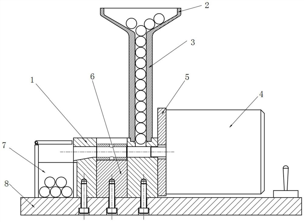
The invention discloses a pneumatic hole extrusion device and a hole extrusion method thereof. The pneumatic hole extrusion device comprises a base, a funnel and an air cylinder, a hole extrusion channel is formed in the base, an air outlet pipeline of the air cylinder is communicated with the inlet side of the hole extrusion channel of the base, and a bead inlet communicated with the hole extrusion channel and a discharging port used for containing a round pipe to be subjected to hole extrusion are further formed in the upper portion of the base. The bead inlet of the base is communicated with the hole extrusion channel so that the round pipe can be placed in the base for hole extrusion, and the lower portion of the guide pipe of the funnel is supported above the bead inlet. Hole extrusion efficiency is low, danger coefficient is high and cost is high due to cooperation of a conventional hydraulic machine and a hole extrusion die, a pneumatic device is adopted for hole extrusion, working efficiency and safety are improved, and the device is particularly suitable for batch production.

Description

technical field [0001] The invention relates to the technical field of hole extrusion, in particular to a pneumatic hole extrusion device and a hole extrusion method. Background technique [0002] It is difficult to guarantee the machining accuracy of the inner hole of round pipe parts, because it is easy to produce local deformation under the action of external force, especially when the workpiece wall thickness error is large or the clamping force is unevenly distributed, the deformation will be more obvious. In addition, during the cutting process, the heat generated will also cause the workpiece to deform, and the deformation is difficult to control due to the different cutting parameters, tools and workpiece materials. In addition, when the workpiece is cut, the cutting force acting on the workpiece, especially the radial cutting force, is prone to vibration, which is more obvious for thin-walled workpieces, resulting in deformation of the workpiece and affecting the ma...

Claims


Application Information

Patent Timeline
IPC IPC(8): B23P9/02B23Q5/22
CPCB23P9/02B23Q5/22Y02P70/10
Inventor 龚甜王祖华涂繁彭俊峰余宇恒朱莎彭林香吴磊
Owner 武汉华夏精冲技术有限公司
Learn More