
Rapid workpiece cutting fluid removing device for numerically controlled lathe

A technology for CNC lathes and cutting fluids, which is applied in metal processing machinery parts, manufacturing tools, metal processing equipment, etc., can solve the problems of incomplete drying of cutting fluid, insignificant contact effect, long drying time, etc., to speed up the drying process. Dry process, easy removal, speed up the effect

Pending Publication Date: 2022-03-04
马志会
View PDF1 Cites 0 Cited by
  • Summary
  • Abstract
  • Description
  • Claims
  • Application Information

AI Technical Summary

Problems solved by technology

[0003] CN102847958A discloses a numerical control lathe, comprising a machine tool body and a control panel arranged on the machine tool body, a guide rail arranged on the machine tool body, a tool rest platform arranged on the upper end of the guide rail, and a cooling device arranged on the tool rest platform, and The toolbox is arranged on the right side of the machine tool body, the drying box is arranged on the right side of the toolbox, and the loading table is arranged at the lower end of the machine tool body. The control panel is also provided with a voice control input device. During processing and use: The iron filings enter the stage, and the cooling cutting fluid enters the lower layer of the stage through the small hole on the stage, so that the iron filings and cutting fluid are separated and loaded, and the iron filings can be dumped just by pulling out the stage, using voice control The input device realizes voice input, which is fast and convenient. After processing, the workpiece can be placed in the drying box to avoid the residue of cutting fluid and cause the workpiece to rust; when removing the cutting fluid on the surface of the workpiece, the cutting fluid is automatically flowed out and put into the drying box. However, there are the following problems: when the workpiece is irregular, the hot air flow is not easy to contact the workpiece, and the effect of static placement of the workpiece and the contact with the hot air flow is not obvious, resulting in incomplete drying of the cutting fluid or a long drying time. There was a problem

Method used


Image

  • Rapid workpiece cutting fluid removing device for numerically controlled lathe
  • Rapid workpiece cutting fluid removing device for numerically controlled lathe
  • Rapid workpiece cutting fluid removing device for numerically controlled lathe

Examples


Embodiment Construction

[0025] The following will clearly and completely describe the technical solutions in the embodiments of the present invention with reference to the accompanying drawings in the embodiments of the present invention. Obviously, the described embodiments are only some, not all, embodiments of the present invention.

[0026] In describing the present invention, it should be understood that the terms "upper", "lower", "front", "rear", "left", "right", "top", "bottom", "inner", " The orientation or positional relationship indicated by "outside", etc. is based on the orientation or positional relationship shown in the drawings, and is only for the convenience of describing the present invention and simplifying the description, rather than indicating or implying that the referred device or element must have a specific orientation, so as to Specific orientation configurations and operations, therefore, are not to be construed as limitations on the invention.

[0027] refer to Figure ...


PUM


Abstract

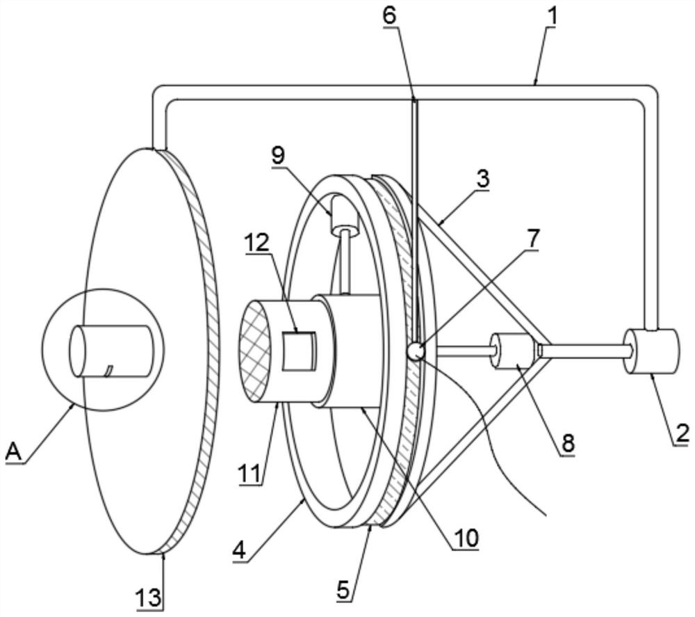
The rapid workpiece cutting fluid removing device for the numerically controlled lathe comprises a support fixed to the lathe, a motor is fixedly connected to the end of the support, two supporting rods are symmetrically fixed to the driving end of the motor, the ends of the two supporting rods are jointly and fixedly connected with a rotating ring, the supporting rods are fixed to the outer wall of the support, and the rotating ring is fixedly connected with the rotating ring. An electric brush is fixedly connected to the end of the supporting rod, an annular groove is formed in the outer wall of the rotating ring, a conducting ring is fixed in the annular groove, the outer wall of the conducting ring makes contact with the outer wall of the electric brush, a motor is fixedly connected to the inner wall of the rotating ring, and the input end of the motor is connected with the conducting ring through a wire. The device has the advantages that multi-dimensional rotation of a workpiece in the rotary drum is achieved through revolution and rotation of the rotary drum, the contact surface of the workpiece and hot air flow is wider, cutting fluid on the surface of the irregular workpiece is conveniently removed, entering of the air flow is guaranteed through cleaning of the dustproof net, sufficient hot air flow in contact with the workpiece is guaranteed, and the drying process is accelerated.

Description

technical field [0001] The invention relates to the technical field of numerically controlled lathes, in particular to a device for quickly removing cutting fluid from workpieces used in numerically controlled lathes. Background technique [0002] CNC lathe is one of the most widely used CNC machine tools. It is mainly used for cutting the inner and outer cylindrical surfaces of shaft parts or disk parts, the inner and outer conical surfaces of any cone angle, the complex rotary inner and outer curved surfaces, and cylindrical and conical threads. The CNC machine tool automatically processes the processed parts according to the pre-programmed processing program. [0003] CN102847958A discloses a numerical control lathe, comprising a machine tool body and a control panel arranged on the machine tool body, a guide rail arranged on the machine tool body, a tool rest platform arranged on the upper end of the guide rail, and a cooling device arranged on the tool rest platform, a...

Claims


Application Information

Patent Timeline
Patent Type & Authority Applications(China)
IPC IPC(8): B23Q11/00
CPCB23Q11/00
Inventor 马志会
Owner 马志会
Learn More