
Formaldehyde removal device

A formaldehyde and diversion device technology, applied in heating and ventilation hoods/covers, mechanical equipment, air-conditioning systems, etc., can solve problems such as high energy consumption, secondary pollution of the environment, and slow air purification speed, and achieve high processing efficiency, The effect of avoiding secondary pollution and low treatment cost

Pending Publication Date: 2022-03-04
国网冀北电力有限公司超高压分公司 +1
View PDF5 Cites 0 Cited by
  • Summary
  • Abstract
  • Description
  • Claims
  • Application Information

AI Technical Summary

Problems solved by technology

[0003] At present, for the indoor environment with high formaldehyde concentration, the more common treatment method is to cultivate green plants, that is, to cultivate green plants indoors, but the green plants themselves purify the air very slowly, and in the absence of relative air flow, The concentration of formaldehyde near the green plants is low, while the concentration of formaldehyde near the walls and furniture is high, which will further reduce the purification rate of formaldehyde in the air by green plants, resulting in little effect of purifying formaldehyde through green plants; another treatment method is to use air Purifier, this type of air purifier has strong pertinence for formaldehyde purification treatment, high treatment efficiency, and can effectively reduce the concentration of formaldehyde in the environment, but if you want to maintain the formaldehyde purification treatment effect, you need to open the air purifier for a long time , to ensure its continuous operation, high energy consumption, and long-term use requires frequent replacement of the filter element of the air purifier to ensure the air purification effect and formaldehyde treatment efficiency, which undoubtedly further increases the use cost of the air purifier; there is also a The treatment method is to use chemical agents that can chemically react with formaldehyde in a targeted manner, and spray these agents on the formaldehyde release sources such as furniture or decoration surfaces. The effect of this treatment method is also good, but because it uses chemical agents Remove formaldehyde in the form of chemical reaction. In actual operation, these chemicals will inevitably cause secondary pollution to the environment, increasing operational risks and safety hazards

Method used


Image

  • Formaldehyde removal device
  • Formaldehyde removal device

Examples


Embodiment Construction

[0039] The core of the present invention is to provide a formaldehyde removal device, which can quickly release formaldehyde contained in various materials and materials in a closed environment into the environment, so as to efficiently treat the formaldehyde.

[0040] In order to enable those skilled in the art to better understand the solution of the present invention, the present invention will be further described in detail below in conjunction with the accompanying drawings and specific embodiments.

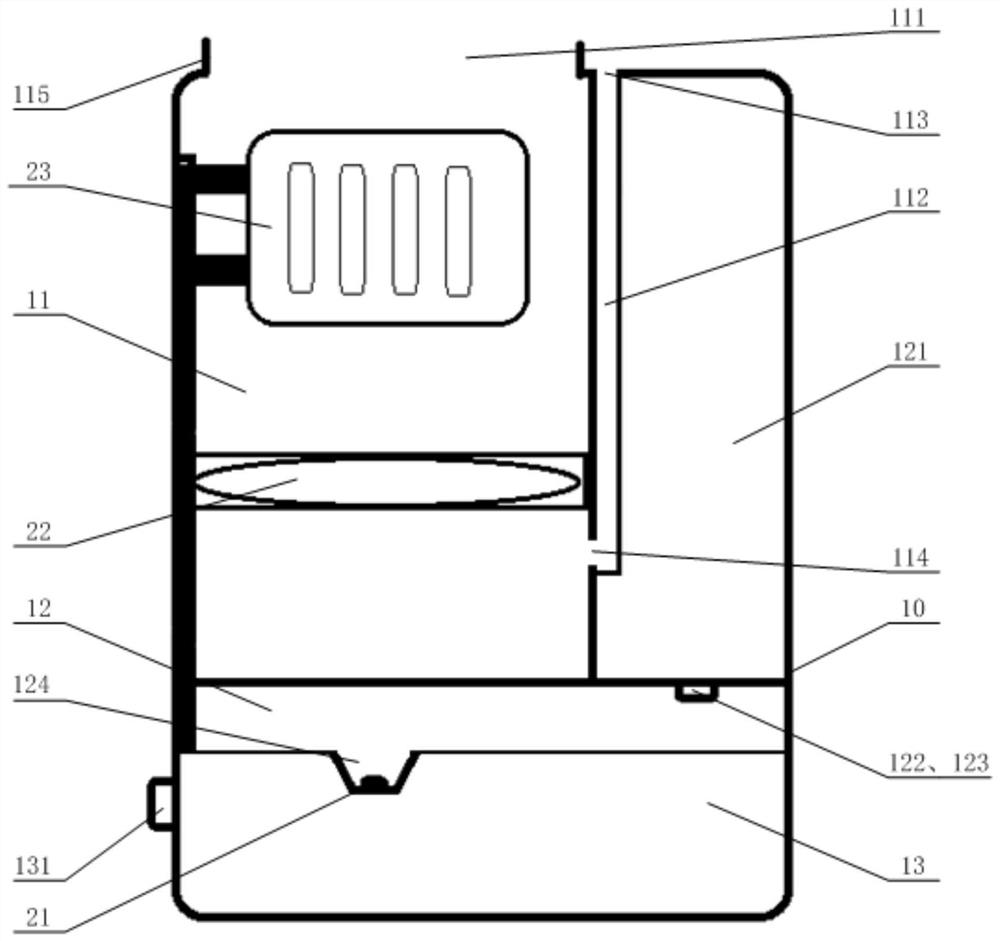
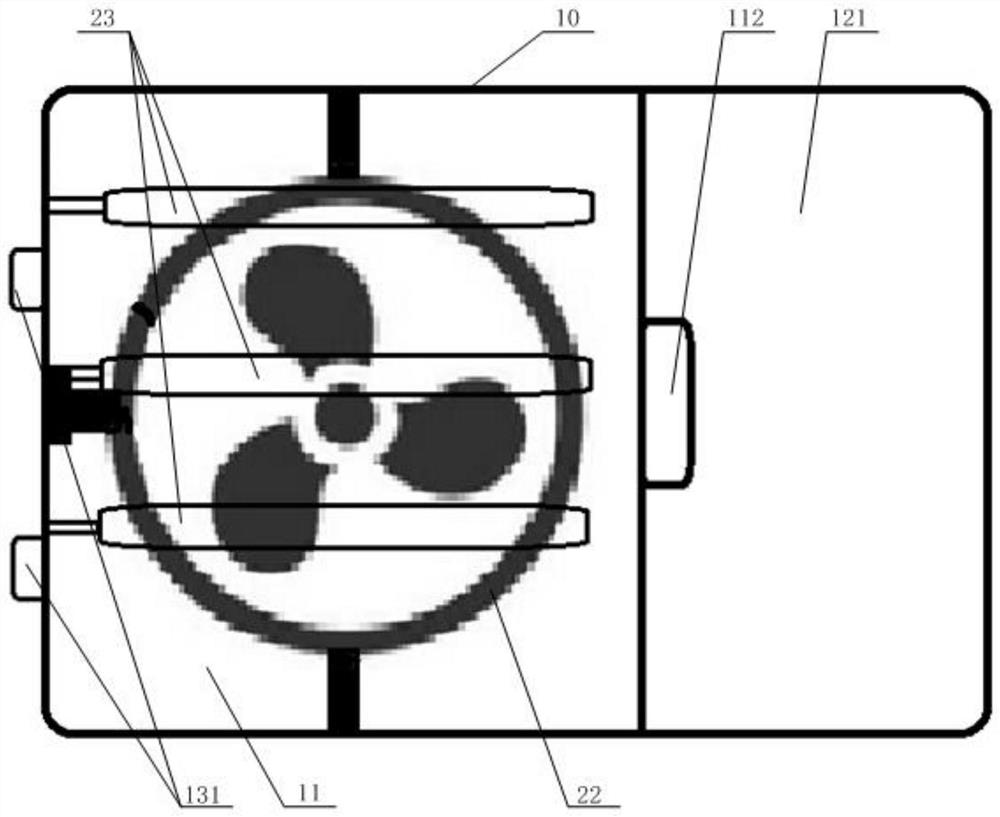
[0041] Please refer to figure 1 and figure 2 , figure 1 A schematic diagram of the assembly structure of the formaldehyde removal device provided for a specific embodiment of the present invention; figure 2 for figure 1 top view.

[0042] In a specific embodiment, the formaldehyde removal device provided by the present invention includes a housing 10, the housing 10 is provided with a wind chamber 11 and a water supply chamber 12 filled with water, the water supply cha...


PUM


Abstract

The invention discloses a formaldehyde removal device which comprises a shell, an air cavity and a water supply cavity containing water are formed in the shell, an atomization device is arranged in the water supply cavity, and a flow guide device and a heating device are arranged in the air cavity. The atomization device, the flow guiding device, the heating device and an air outlet of the air cavity are sequentially arranged in the airflow direction and communicate with one another. According to the formaldehyde removal device, formaldehyde contained in various materials in a closed environment can be quickly released into the environment, so that the formaldehyde can be efficiently treated.

Description

technical field [0001] The invention relates to the technical field of displacement sensor detection matching components, in particular to a formaldehyde removal device. Background technique [0002] In daily life, especially when it comes to interior decoration and the use environment of newly installed furniture, the existence of formaldehyde has caused extremely serious damage to the health of indoor personnel such as users. Therefore, how to quickly and efficiently remove formaldehyde in the daily environment is a problem that has attracted increasing attention. [0003] At present, for the indoor environment with high formaldehyde concentration, the more common treatment method is to cultivate green plants, that is, to cultivate green plants indoors, but the green plants themselves purify the air very slowly, and in the absence of relative air flow, The concentration of formaldehyde near the green plants is low, while the concentration of formaldehyde near the walls an...

Claims


Application Information

Patent Timeline
IPC IPC(8): F24F8/133F24F8/80F24F11/72F24F11/89F24F13/20
CPCF24F11/72F24F11/89F24F13/20
Inventor 张晓义赵振峰赵波果淼董伟杨丽华于文博付徐笙
Owner 国网冀北电力有限公司超高压分公司
Learn More