Supercharge Your Innovation With Domain-Expert AI Agents!

Positive end-expiratory pressure valve for portable breathing machine and control method of positive end-expiratory pressure valve

A positive end-expiratory pressure, ventilator technology, applied in respirator and other directions, can solve the problems of slow PEEP adjustment response, complex mechanical structure, high air source requirements, and achieve great flexibility and convenience, simple mechanical mechanism, control Simple process effect

Active Publication Date: 2022-03-08
SHANDONG UNIV +1
View PDF12 Cites 0 Cited by
  • Summary
  • Abstract
  • Description
  • Claims
  • Application Information

AI Technical Summary

Problems solved by technology

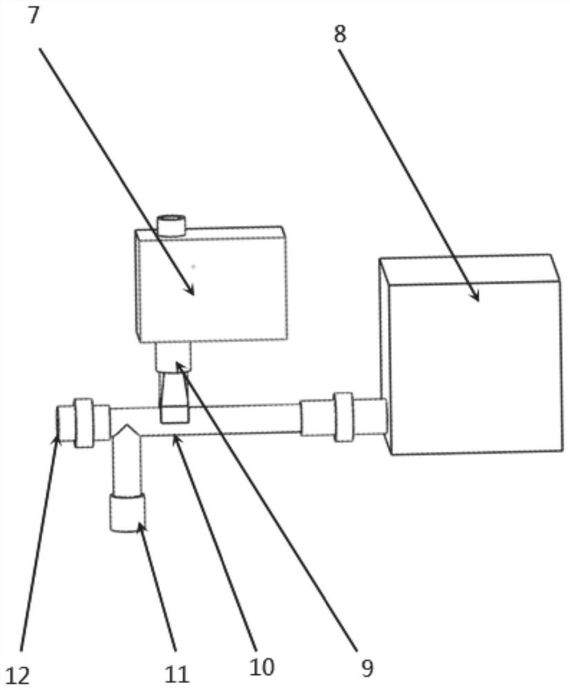
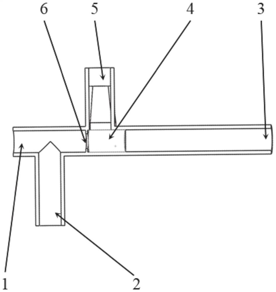
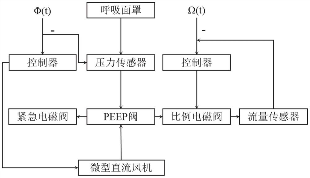
[0006] There are currently three main types of PEEP valves: the first type is mechanical PEEP valves. This type of PEEP valve controls the output pressure of the PEEP valve through a complex mechanical structure and manual adjustment of the spring. Its PEEP value has poor accuracy, large volume, and is easily damaged. , it is not convenient for the continuous adjustment of PEEP; the second type is motor-controlled PEEP valve, the control system of this type of PEEP valve is cumbersome and the mechanical structure is complicated; the third type is pneumatic control PEEP valve, this type of PEEP valve is commonly used in modern ventilators. , but its PEEP adjustment response is slow and requires high air source

Method used


Image

  • Positive end-expiratory pressure valve for portable breathing machine and control method of positive end-expiratory pressure valve
  • Positive end-expiratory pressure valve for portable breathing machine and control method of positive end-expiratory pressure valve
  • Positive end-expiratory pressure valve for portable breathing machine and control method of positive end-expiratory pressure valve

Examples


Embodiment Construction

[0039] The present invention will be further described below in conjunction with the accompanying drawings and embodiments.

[0040] It should be noted that the following detailed description is exemplary and intended to provide further explanation of the present invention. Unless defined otherwise, all technical and scientific terms used herein have the same meaning as commonly understood by one of ordinary skill in the art to which this invention belongs.

[0041] It should be noted that the terminology used here is only for describing specific embodiments, and is not intended to limit exemplary embodiments according to the present invention. As used herein, unless the context clearly dictates otherwise, the singular is intended to include the plural, and it should also be understood that when the terms "comprising" and / or "comprising" are used in this specification, they mean There are features, steps, operations, means, components and / or combinations thereof.

[0042] Th...


PUM


Abstract

The invention provides an end-expiratory positive pressure valve for a portable breathing machine and a control method thereof.The end-expiratory positive pressure valve comprises a valve body, a connecting pipeline, a control valve, a controller and an electromagnetic valve, the valve body is provided with a first inlet, a second inlet, a first outlet and a second outlet, the first inlet is provided with the connecting pipeline used for being connected with a breathing mask, and the second inlet is provided with the control valve; the second inlet is connected to a low-pressure gas source through a connecting pipeline, the first outlet is configured to be conducted when the gas acting force of the first inlet borne by the valve element is larger than that of the second inlet, gas in the valve body enters the first outlet, and a control valve used for controlling the flow of the outlet is arranged at the first outlet; the controller is configured to open the electromagnetic valve when the valve body works abnormally or the positive end-expiratory pressure value exceeds a set value, and the opening degree of the control valve and the supply speed of the low-pressure gas source are controlled according to the positive end-expiratory pressure value. The positive end expiratory pressure valve is simple in structure, high in response speed and capable of achieving linear adjustment of the PEEP value.

Description

technical field [0001] The invention belongs to the technical field of positive end-expiratory pressure valves, and in particular relates to a positive end-expiratory pressure valve for a portable ventilator and a control method thereof. Background technique [0002] The statements in this section merely provide background information related to the present invention and do not necessarily constitute prior art. [0003] Positive end expiratory pressure (Positive End Expiratory Pressure, PEEP) refers to maintaining a positive expiratory pressure during the exhalation phase, and a state where the end-expiratory airway pressure is greater than 0Pa. PEEP should generally be maintained at 300Pa to 1000Pa. PEEP is mainly used in the following situations: expand and close the alveoli, reduce the venous arterial blood shunt during expiration, reduce or eliminate shear stress injury, and increase the arterial oxygen partial pressure (Alveolar Oxygen Partial Pressure, PaO 2 ) for th...

Claims


Application Information

Patent Timeline
IPC IPC(8): A61M16/20
CPCA61M16/203
Inventor 李可丁博智陈玉国徐峰王甲莉边圆庞佼佼潘畅李贻斌徐凤阳蒋丽军
Owner SHANDONG UNIV
Features
  • R&D
  • Intellectual Property
  • Life Sciences
  • Materials
  • Tech Scout
  • Unparalleled Data Quality
  • Higher Quality Content
  • 60% Fewer Hallucinations
Learn More