Electrode detection method and system

A detection method and electrode technology, which can be applied to measurement devices, electrochemical variables of materials, material analysis by electromagnetic means, etc., can solve the problems of easy loss of ion adsorption, difficulty in adsorbing heavy metal ions, and affecting the effect of soil treatment. To ensure the effect of soil treatment, improve accuracy and reduce waste of resources

Pending Publication Date: 2022-03-08
长沙稷下科技咨询有限公司
View PDF0 Cites 0 Cited by
  • Summary
  • Abstract
  • Description
  • Claims
  • Application Information

AI Technical Summary

Problems solved by technology

[0004] In view of the related technologies mentioned above, the inventor believes that with the increase of the number of times of use and / or the increase of the use time, the electrode is easy to lose the ion adsorption effect. At this time, it is difficult to play the role of adsorbing heavy metal ions when the electrode is inserted into the soil and energized. Affected the effect of soil treatment

Method used


Image

  • Electrode detection method and system
  • Electrode detection method and system
  • Electrode detection method and system

Examples


Embodiment 1

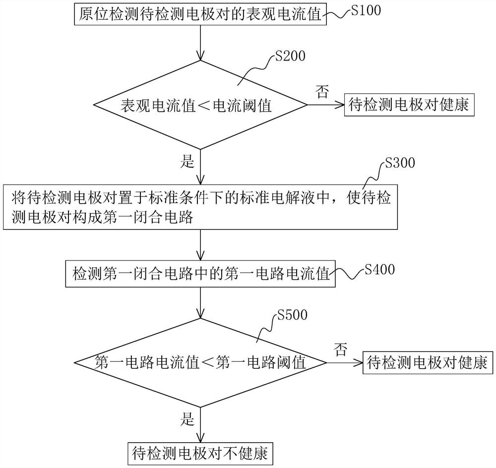
[0107] refer to Figure 4 , including a current detection module 1 and a standard test module 2. The current detection module 1 is used to detect the apparent current value of the electrode pair to be detected in situ; it is also used to detect the first circuit in the first closed circuit formed by the electrode pair to be detected in the standard test module 2 based on a constant voltage DC power supply current value.

[0108] The standard test module 2 is used to contain the standard electrolyte; it is also used to insert the electrode pair to be tested, so that the electrode pair to be tested can form a first closed circuit based on a constant voltage DC power supply.

[0109] Among them, the in-situ detection refers to the detection of the apparent current value of the electrode pair to be detected when the electrode pair to be detected is located in the polluted soil. The electrode pair to be detected is inserted into the polluted soil. The apparent current value refe...

Embodiment 2

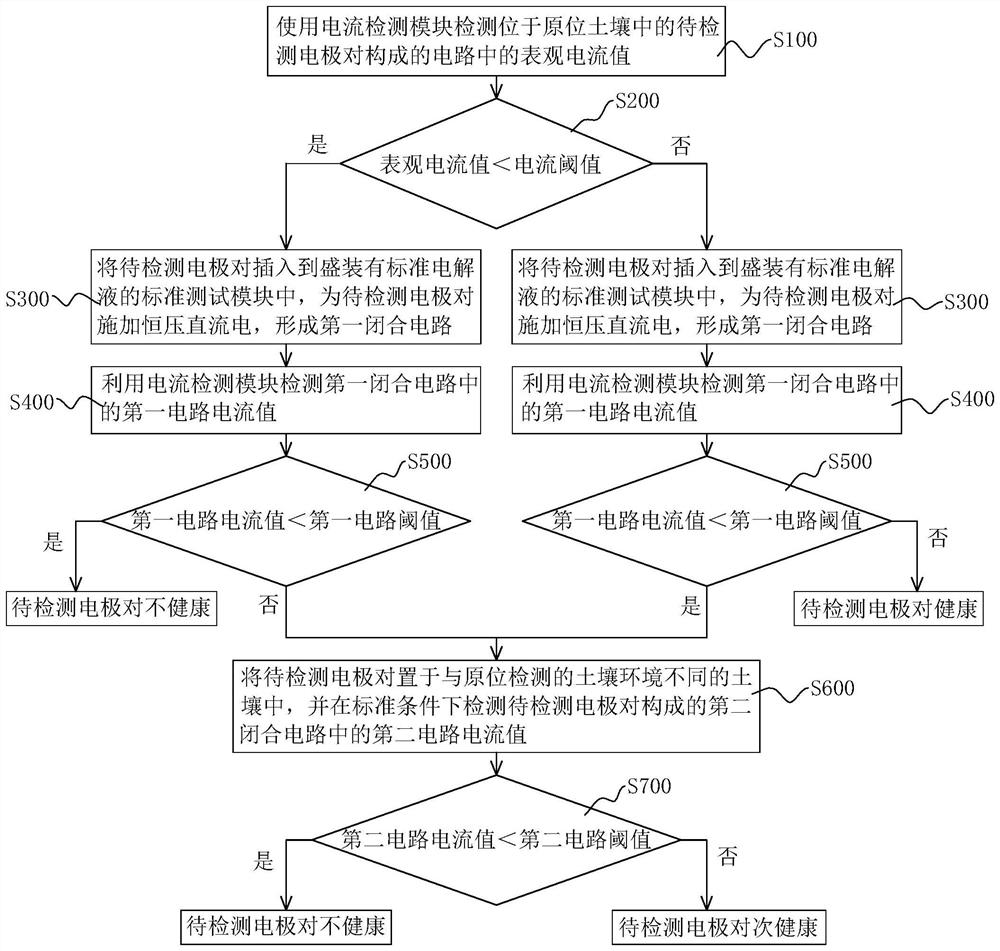
[0124] refer to Figure 8 , the difference from Embodiment 1 is that the electrode detection system also includes a soil module 3, which is used to hold soil different from the soil environment of the in-situ soil where the electrode to be detected is located; less than the current threshold, but the first circuit current value is greater than or equal to the first circuit threshold, or the apparent current value is greater than or equal to the current threshold, but the first circuit current value is less than the When the threshold of the first circuit is reached, the electrode pair to be detected is inserted, so that the electrode pair to be detected forms a second closed circuit based on a constant voltage DC power supply. Wherein, the structure of the soil module 3 may be the same or similar to that of the standard test module 2 or can play a corresponding role, and will not be repeated here. The soil environment different from the in-situ soil where the electrode pair t...


PUM


Abstract

The invention relates to an electrode detection method and system. The method comprises the steps that the apparent current value of a to-be-detected electrode pair is detected in situ; when the apparent current value is smaller than a preset current threshold value, the electrode pair to be detected is placed in a standard electrolyte under a standard condition, so that the electrode pair to be detected forms a first closed circuit; detecting a first circuit current value in the first closed circuit; when the first circuit current value is smaller than a preset first circuit threshold value, the electrode pair to be detected is determined to be in an unhealthy state; and when the first circuit current value is greater than or equal to the first circuit threshold value, determining that the electrode pair to be detected is in a healthy state. The electrode pair to be detected in an unhealthy state can be subjected to cleaning treatment and electrochemical repair treatment, so that the electrode pair to be detected meets regeneration conditions and can be repeatedly used. And it is conveniently guaranteed that in subsequent contaminated soil treatment, the electrode can have the ion adsorption effect, and therefore the soil treatment effect is conveniently guaranteed.

Description

technical field [0001] The invention relates to the field of soil treatment, in particular to an electrode detection method and system. Background technique [0002] Soil pollution is an environmental problem that the current society must face, especially for heavy metal pollution in soil, which is difficult to deal with and high in cost. The existing treatment methods mainly include soil replacement method, solidification method, leaching method, phytoremediation method and electric restoration method. Among them, the electric repair method is widely used because of its low cost and good effect. [0003] The electrokinetic remediation method in the related art mainly removes heavy metals in soil through the composite action of electrochemistry and electrokinetics. Specifically, an electrode is inserted into the polluted soil and a direct current is applied, a direct current electric field is formed between the two electrodes, and a complete electric field is formed by usi...

Claims


Application Information

Patent Timeline
Patent Type & Authority Applications(China)
IPC IPC(8): B09C1/08G01N27/00G01N27/26
CPCB09C1/085G01N27/00G01N27/26B09C2101/00
Inventor 陈毫高平梁海鹏金鑫
Owner 长沙稷下科技咨询有限公司
Why Eureka
Try Eureka