In-situ high-pressure dosing device for treatment of contaminated soil

A technology of polluted soil and dosing device, which is applied in the field of soil treatment, can solve the problems of dilution of medicine solution, uneven mixing, affecting the effect of soil pollution treatment, lack of design of medicine solution mixing, etc., so as to improve the treatment effect and ensure the soil treatment effect , the effect of effective mixed processing

Inactive Publication Date: 2020-11-24
万物生(苏州)环境科技有限公司
View PDF9 Cites 0 Cited by
  • Summary
  • Abstract
  • Description
  • Claims
  • Application Information

AI Technical Summary

Problems solved by technology

However, the structural design of the above-mentioned patents is relatively simple, and the mixing design of the liquid medicine is relatively lacking. It is easy to affect the treatment effect of soil pollution due to the dilution and uneven mixing of the liquid medicine, so there are certain limitations.

Method used


Image

  • In-situ high-pressure dosing device for treatment of contaminated soil
  • In-situ high-pressure dosing device for treatment of contaminated soil
  • In-situ high-pressure dosing device for treatment of contaminated soil

Examples


Embodiment 1

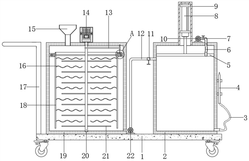
[0026] refer to Figure 1-2 , an in-situ high-pressure dosing device for polluted soil treatment, comprising a base 1 on which moving wheels are fixed at the four corners of the bottom outer wall by bolts, and a mixing tank 19 and a dosing tank 2 are respectively fixed on both sides of the top outer wall of the base 1 by bolts, The top of the dosing tank 2 is welded with a fixed cylinder 9, and the inner wall of the fixed cylinder 9 is fixed with a hydraulic rod 8 by bolts, and the end of the extension rod of the hydraulic rod 8 is fixed with a piston plate 5 by bolts, and the top outer wall of the dosing tank 2 One side is fixed with an air pump 10 by bolts, the output end of the air pump 10 is fixedly connected with an output pipe, and the opposite side of the output pipe and the piston plate 5 is fixedly connected with a corrugated hose-6, and one end of the output pipe is fixedly connected with a seal The valve 7 is welded with a discharge port on one side of the bottom of...

Embodiment 2

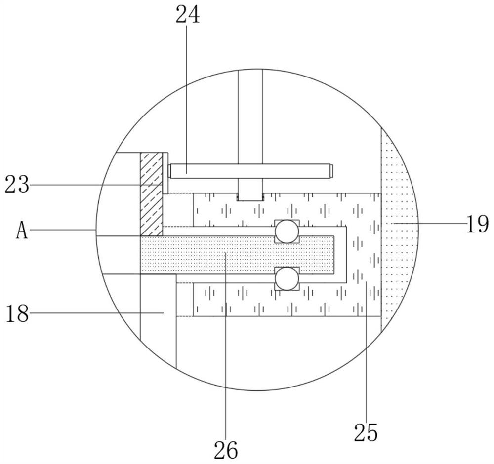
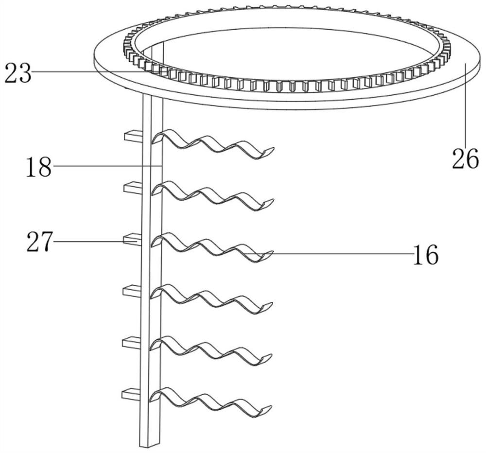
[0034] refer to image 3 , an in-situ high-pressure dosing device for contaminated soil treatment. Compared with Embodiment 1, this embodiment also includes that the other side of the mixing rod 18 is welded with convex plates 27 distributed equidistantly.

[0035] Working principle: When in use, the protruding plate 27 on the other side of the mixing rod 18 is used to rotate with the rotating plate 26 to effectively improve the mixing effect of the mixing rod 18 on the medicinal solution, thereby achieving the purpose of further improving the subsequent soil treatment effect.


PUM


Abstract

The invention discloses an in-situ high-pressure dosing device for treatment of contaminated soil. The in-situ high-pressure dosing device comprises a base, wherein traveling wheels are fixed to fourcorners of the external wall of the bottom of the base through bolts, a mixing tank and a dosing tank are fixed to two sides of the external wall of the top of the base respectively through bolts, a fixed cylinder is welded to the top end of the dosing tank, a hydraulic lever is fixed to the internal wall of the fixed cylinder through bolts, a piston plate is fixed to the end part of a stretchingrod of the hydraulic lever through bolts, an inflator pump is fixed to one side of the external wall of the top of the dosing tank through bolts, an output end of the inflator pump is fixedly connected with an output pipe, one side, opposite to the piston plate, of the output pipe is fixedly connected with a corrugated hose I, and one end of the output pipe is fixedly connected with a sealing valve. According to the in-situ high-pressure dosing device for treatment of the contaminated soil, through the arranged hydraulic lever, the piston plate is convenient to push; and through being matchedwith inflating and pressurizing actions of the inflator pump and the corrugated hose I, the internal pneumatic pressure of the dosing tank is effectively improved, and thus, proceeding of subsequent dosing operation is facilitated.

Description

technical field [0001] The invention relates to the technical field of soil treatment, in particular to an in-situ high-pressure dosing device for polluted soil treatment. Background technique [0002] Soil pollutants can be roughly divided into two categories: inorganic pollutants and organic pollutants. Inorganic pollutants mainly include acids, alkalis, heavy metals, salts, compounds of radioactive elements cesium and strontium, compounds containing arsenic, selenium and fluorine, etc. Organic pollutants mainly include organic pesticides, phenols, cyanides, petroleum, synthetic detergents, and harmful microorganisms brought by urban sewage, sludge, and manure. When treating polluted soil, it is often necessary to add chemicals to the soil. [0003] For example, the invention patent with the Chinese patent application number CN2017217864575 discloses an in-situ high-pressure dosing device for polluted soil treatment, including a base and a linear motor. Atomizing nozzle...

Claims


Application Information

Patent Timeline
IPC IPC(8): B01F7/18B01F15/02B09C1/00
CPCB09C1/00B09C2101/00B01F27/84B01F27/902B01F35/717
Inventor 郭小品
Owner 万物生(苏州)环境科技有限公司
Why Eureka
Try Eureka