
Bio-boiler large dust automatic cleaning heat recovery equipment

An automatic cleaning and heat recovery technology, which is applied in lighting and heating equipment, combustion equipment, solid fuel pretreatment, etc., can solve the problems of heat recovery, waste, and heat loss of flue gas that cannot be used at high temperatures, and avoid excessive moisture in fuel. More, full combustion, high combustion efficiency

Pending Publication Date: 2022-03-08
上海岳合机电科技有限公司
View PDF0 Cites 0 Cited by
  • Summary
  • Abstract
  • Description
  • Claims
  • Application Information

AI Technical Summary

Problems solved by technology

[0003] However, the high-temperature flue gas discharged from the existing biomass boilers is generally discharged directly after treatment, and the heat of the high-temperature flue gas cannot be effectively recycled, resulting in a large amount of heat energy loss and relatively wasteful. Therefore, we propose a biological Boiler large dust automatic cleaning heat recovery equipment to solve the above mentioned problems

Method used


Image

  • Bio-boiler large dust automatic cleaning heat recovery equipment
  • Bio-boiler large dust automatic cleaning heat recovery equipment
  • Bio-boiler large dust automatic cleaning heat recovery equipment

Examples


Embodiment 1

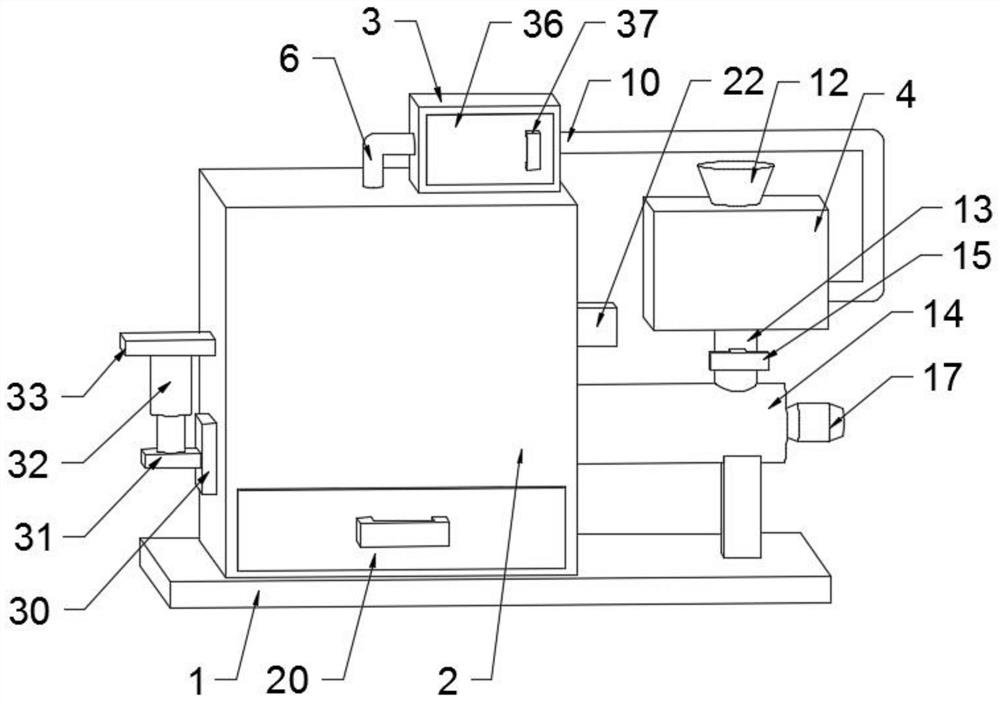
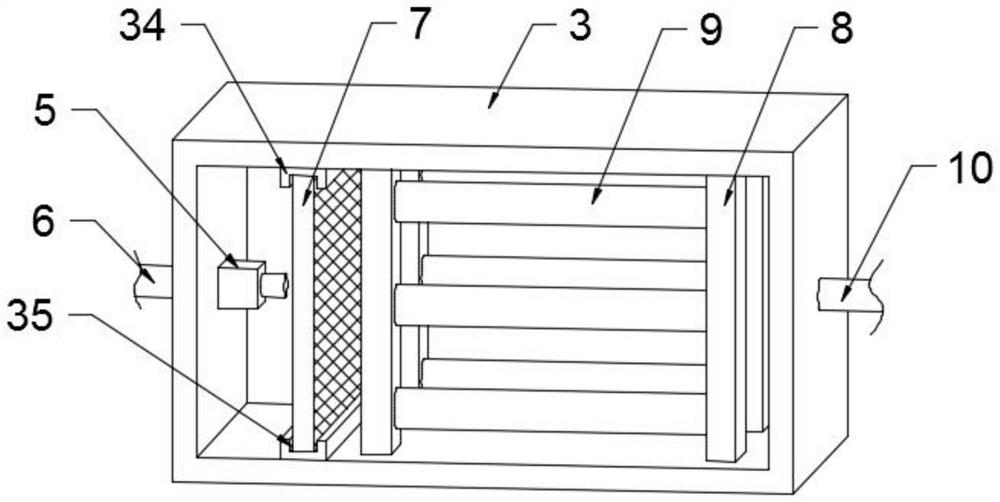
[0028] see Figure 1-Figure 5 , in the embodiment of the present invention, the bio-boiler large dust automatic cleaning heat recovery equipment includes a base 1, which is used to support and place the boiler body 2, and the boiler body 2 fixedly connected to the upper end of the base 1 is used to support and fix the filter box 3, which is fixedly connected The filter box 3 at the upper end of the boiler body 2 is used to support and place the filter screen 7 and the dust bag 9, and the discharge box 4 fixedly arranged on the right side of the boiler body 2 is used to store fuel and also includes a recovery component;

[0029] The recovery assembly is used to recover the heat in the exhaust gas generated inside the boiler body 2, the recovery assembly is fixedly arranged between the filter box 3 and the discharge box 4, the recovery assembly includes an aspirator 5, and the suction The suction machine 5 is fixedly installed on the left inner wall of the filter box 3, and is u...

Embodiment 2

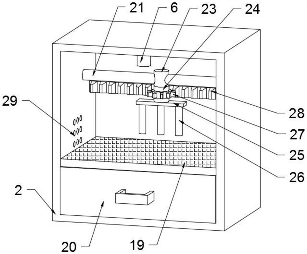
[0038] The difference from Embodiment 1 is that: the inner walls of the left and right sides of the boiler body 2 are rotatably connected with reciprocating screw rods 21, which are used to drive the screw rod sleeves 23 to move left and right. The output end of the reciprocating screw rod 21 is fixedly connected, and the rotating motor 22 is fixedly installed on the right side outer wall of the boiler body 2 to drive the reciprocating screw rod 21 to rotate. The outer fixed sleeve of the reciprocating screw rod 21 is provided with a screw rod cover 23 for use To drive the rotating rod 24 to move left and right, the lower end of the screw mandrel cover 23 is rotatably connected with a rotating rod 24, which is used to drive the fixed plate 25 to move left and right, and the lower end of the rotating rod 24 is fixedly connected with a fixed plate 25, which is used to drive the stirring The rod 26 moves left and right, and the lower end of the fixed plate 25 is fixedly connected ...


PUM


Abstract

The invention discloses biological boiler large dust automatic cleaning heat recovery equipment which comprises a base, a boiler body, a filter box and a discharging box and is provided with a recovery assembly, the recovery assembly comprises an air suction machine fixedly installed on the inner wall of the left side of the filter box, the output end of the air suction machine is fixedly connected with an air suction pipe, and the air suction pipe extends into the boiler body; a filter screen is fixedly arranged in the filter box, a plurality of groups of supporting rods are fixedly arranged in the filter box, a dust removal cloth bag is fixedly arranged between the left group of supporting rods and the right group of supporting rods, an exhaust pipe is fixedly arranged on the right side of the filter box, and the end, away from the filter box, of the exhaust pipe penetrates through the right side wall of the discharging box and is communicated with the interior of the discharging box; residual heat in waste gas can be recycled, fuel is heated and dried, water on the surface and in the fuel is reduced, the combustion efficiency is higher when the fuel enters the boiler body to be combusted, and the situation that the combustion effect of the fuel is affected due to excessive water in the fuel is avoided.

Description

technical field [0001] The invention relates to the technical field of biological boilers, in particular to heat recovery equipment for automatic cleaning of large dust in biological boilers. Background technique [0002] Biomass boiler is a type of boiler, that is, the boiler that uses biomass energy as fuel is called biomass boiler, which is divided into biomass steam boiler, biomass hot water boiler, biomass hot air stove, biomass heat conduction Material boilers, horizontal biomass boilers, etc. [0003] However, the high-temperature flue gas discharged from the existing biomass boilers is generally discharged directly after treatment, and the heat of the high-temperature flue gas cannot be effectively recycled, resulting in a large amount of heat energy loss and relatively wasteful. Therefore, we propose a biological Boiler large dust automatic cleaning heat recovery equipment to solve the above-mentioned problems. Contents of the invention [0004] The purpose of t...

Claims


Application Information

Patent Timeline
Patent Type & Authority Applications(China)
IPC IPC(8): F23B30/00F23J15/02F26B9/06F26B21/14F23K3/16F23M20/00F23L1/00B01D46/02B01D46/10B01D46/62B01D46/42
CPCF23B30/00F23J15/025F26B9/06F26B21/14F23K3/16F23M20/00F23L1/00B01D46/02B01D46/10B01D46/4227F23J2217/10F23K2201/20Y02P70/10
Inventor 冯宾杨淦荃杨佩如
Owner 上海岳合机电科技有限公司
Learn More