Efficient household radiator

A radiator and household technology, applied in the field of high-efficiency household radiators, can solve the problems of a single radiator structure and poor heat dissipation effect, and achieve the effects of improving uniformity, heating speed, heat dissipation efficiency, and increasing speed.

Active Publication Date: 2022-03-08
济南圣雅诺暖通科技发展有限公司
View PDF10 Cites 2 Cited by
  • Summary
  • Abstract
  • Description
  • Claims
  • Application Information

AI Technical Summary

Problems solved by technology

[0004]The purpose of the present invention is to solve the problem of single structure and poor heat dissipation effect of household radiators in the prior art, and propose a high-efficiency household radiator

Method used


Image

  • Efficient household radiator
  • Efficient household radiator
  • Efficient household radiator

Examples


Embodiment 1

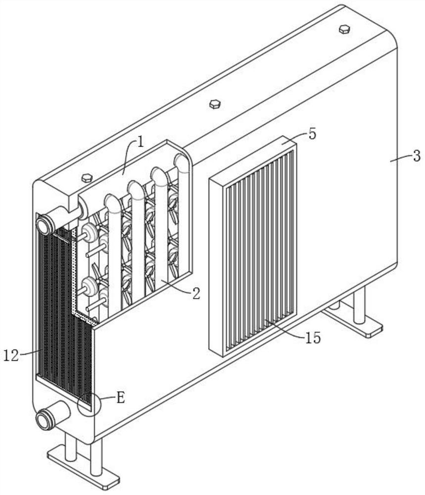
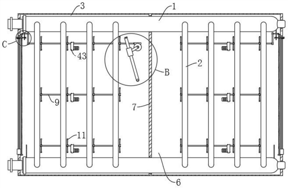
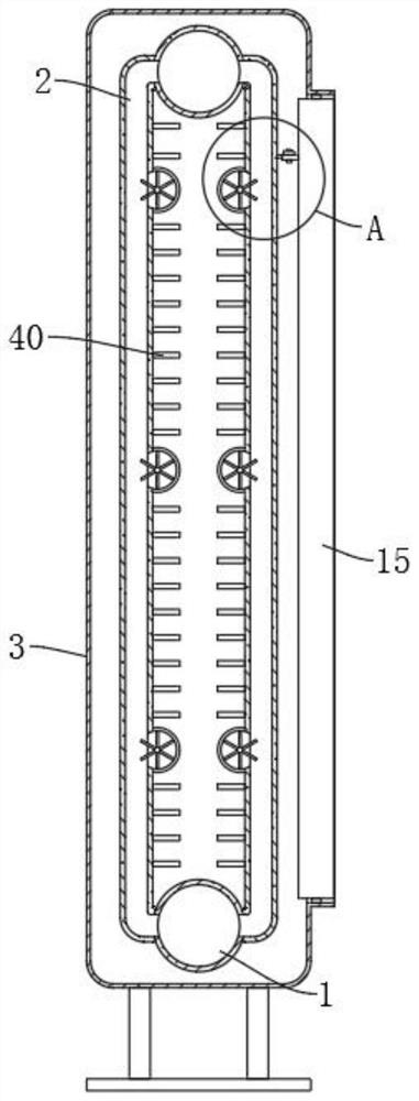
[0034] Refer Figure 1-9A highly efficient home heat sink, including two upper and lower symmetrical set of main water pipes, further comprising: two sets of symmetrical set of heat dissipating tubes 2, allocating between two main water pipes 1, wherein the main water pipe 1 is The outer wall sleeve of the heat dissipation tube 2 is provided with a casing 3, and both ends of the casing 3 are provided with an opening 4, and the two openings 4 are fixedly mounted with a dustproof mesh 13 and a plurality of parallel vertical rods 12, and the shell 3. The distal wall is provided with a vent 5, and the middle portion of the casing 3 is fixedly coupled to the separator 7, and both sides of the separator 7 are provided with a collector cavity 6; a plurality of housing 8, eccentricly fixed to multiple heat dissipation The tube 2 is connected to it, wherein the plurality of housing 8 are rotated by the rotary shaft 9 by rotating the shaft 9, and the casing 3 is provided with a plurality of ...

Embodiment 2

[0039] Refer Figure 2-6 and Figure 8 The same is substantially the same as in Example 1, and further: the swing mechanism includes a worm wheel 19 that is rotatably coupled to the inner wall of the casing 3 by the second turn rod 18, wherein one end of one of the rotating shafts 9 is connected to the worm wheel 19 meshing with the worm wheel through the first clutch 31. The connected worm 20, the shaft end of the worm wheel 19 is fixed to the crank 21, and the inner wall of the casing 3 is rotated by the rotating seat 16, and the outer wall of the pendulum 17 is slidably connected to the sliding sleeve 22, the end and sliding of the crank 21. The outer wall of the sleeve 22 is connected, and the rear wall of the plurality of air wind panels 15 is provided with a crossbar 24, and the rear wall of the plurality of air strip 15 is rotated from the crossbar 24, and the swing end of the crossbar 24 and the swing rod 17 passes through The drawing cord 23 is fixed, and when the rotation ...

Embodiment 3

[0042] Refer figure 2 and Figure 7 It is basically the same as that of Example 1, further in the case where the left and right ends of the housing 3 are rotated through the mounting seat 25, and the outer wall sleeve of the backup screw 26 is provided with it. The reciprocating slider 27, the side wall of the reciprocating slider 27 extends to the outer wall of the housing 3, the side wall of the dust network 13 is provided with a slide with the reciprocating slider 27, and the side wall of the reciprocating slider 27 passes the automatic shrinkage mechanism. The plurality of cleaning rod 35 is connected to the brush 37, and the plurality of cleaning rods 35 are located within the gap of the plurality of vertical rods 12, and the end of the brush 37 abuts the outer wall of the dust-proof mesh 13, wherein one mounting seat 25 rotates There is a transmission shaft 28, and one end of the transmission shaft 28 is engaged between one end of the reciprocating screw 26, and the other end...


PUM


Abstract

The invention discloses an efficient household radiator, and belongs to the field of household radiators. The efficient household radiator comprises two main water pipes which are symmetrically arranged up and down, and further comprises two sets of radiating pipes which are symmetrically arranged and fixedly connected between the two main water pipes, the outer walls of the main water pipes and the radiating pipes are sleeved with a housing, openings are formed in the two ends of the housing, and the two ends of the housing are provided with heat dissipation pipes. A dustproof net and a plurality of parallel vertical rods are fixedly mounted in each of the two openings, an air outlet is formed in the middle of the front side wall of the housing, a partition plate is fixedly connected to the middle of the housing, and air collecting cavities are formed in the two sides of the partition plate; the shells are eccentrically and fixedly connected to the side walls of the heat dissipation pipes; the heat dissipation efficiency of the household radiator can be greatly improved, the obvious temperature difference condition of the indoor temperature can be greatly reduced, and the increasing speed of the indoor temperature is indirectly increased.

Description

Technical field [0001] The present invention relates to the technical field of household radiators, and more particularly to an efficient household radiator. Background technique [0002] Household radiators mainly refer to all kinds of heating and radiators used in home and similar places, also known as civilian radiators. Household radiators make people liberate from heavy, trivial, and time-consuming Chai Wumei stoves to liberate, create more comfortable and beautiful, more comfortable and healthy living and working environment. It is the main terminal equipment of the home heating system in the winter, has become a necessity for modern family life. [0003] The existing heat sink typically passes the internal liquid temperature through the plurality of casing to heat into the air, thereby tonifying the chamber, but the heat dissipation efficiency of such passive heat dissipation is low, often occurring a high temperature around the radiator, The space temperature away from th...

Claims


Application Information

Patent Timeline
Patent Type & Authority Applications(China)
IPC IPC(8): F24D19/00F24D19/08F28G1/02F28G15/06
CPCF24D19/0073F24D19/008F24D19/083F28G1/02F28G15/06
Inventor 李鹏李成喜
Owner 济南圣雅诺暖通科技发展有限公司
Why Eureka
Try Eureka