Glass lining on-line damage detection device and detection method thereof
A damage detection and glass-lined technology, which is applied in the field of glass-lined online damage detection devices, can solve problems such as time-consuming and laborious, undetectable enamel equipment, and small use restrictions of detection devices, so as to achieve accurate detection results, save time and effort in the detection process, and use Limit the effect of small
- Summary
- Abstract
- Description
- Claims
- Application Information
AI Technical Summary
Problems solved by technology
Method used
Image
Examples
Embodiment 1
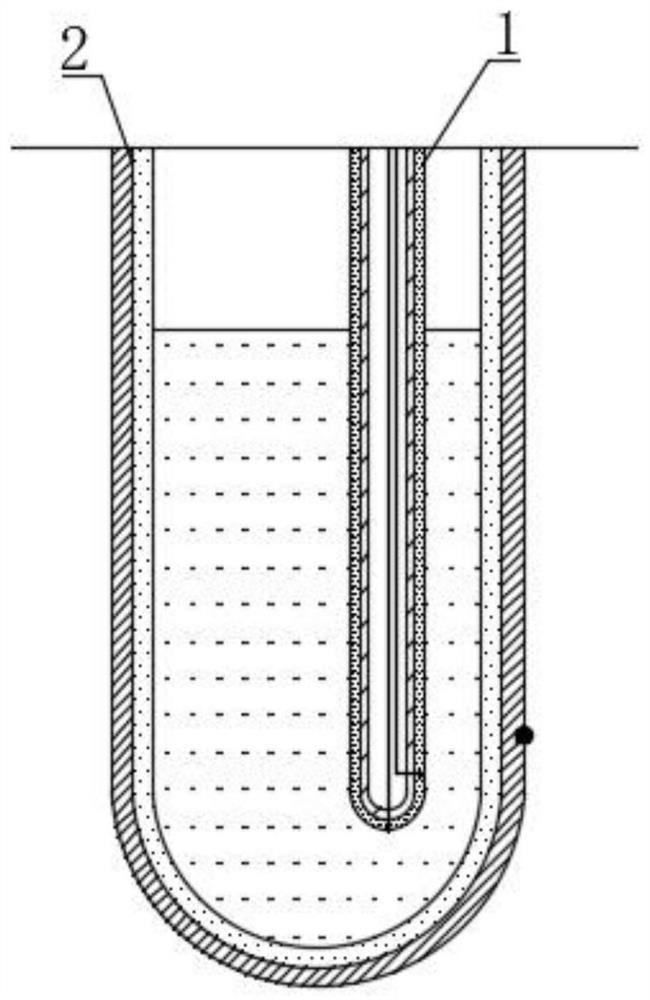
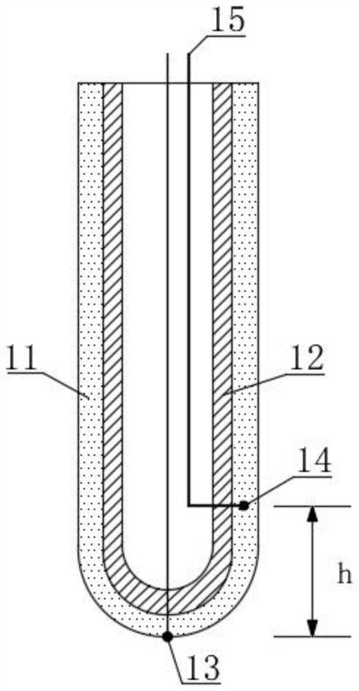
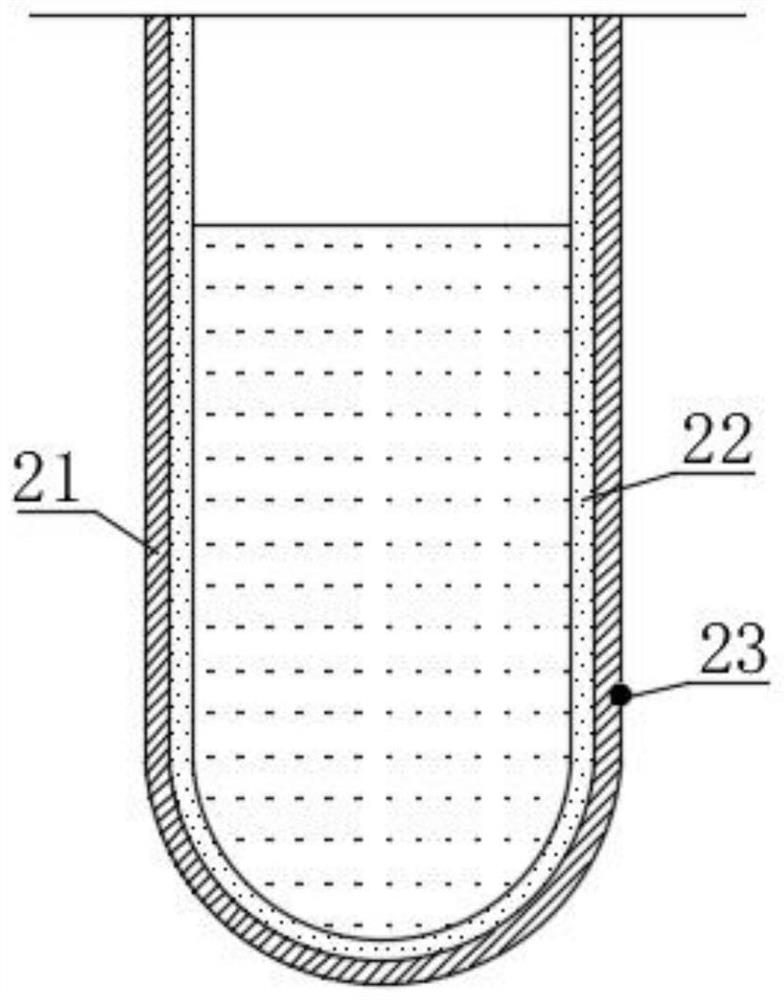
[0051] like Figure 1-4 As shown, a glass-lined online damage detection device proposed by the present invention includes a detection probe 1 and a wireless control terminal 7. The detection probe 1 and the wireless control terminal 7 are connected by wireless transmission, and the detection process is performed through the wireless control terminal 7. The control and display of test data and test results are helpful for use. The test probe 1 is inserted into the enamel equipment 2 to be tested (due to the needs of the test principle, the material filled inside the enamel equipment 2 to be tested must have conductivity, which can be passed Conductivity meter detects and obtains the conductive parameters of the filler to determine whether it is applicable), the enamel equipment 2 to be tested includes two layers, the inner layer and the outer layer, and the inner layer is the second enamel layer 22, the outer layer is the second metal carrier layer 21, and the second The outer ...
Embodiment 2
[0056] like Figure 5-7 As shown, the difference between this embodiment and Embodiment 1 is that the top of the detection probe 1 is installed with a vertically arranged first electric telescopic rod 4, and the end of the first electric telescopic rod 4 away from the detection probe 1 is connected to the fixed block 3, The side wall of the fixed block 3 is equipped with a second electric telescopic rod 5 arranged horizontally, and the end of the second electric telescopic rod 5 away from the fixed block 3 is connected to a stable clamping assembly 6; before detection, the first electric telescopic rod 4 Adjust the height of the detection probe 1, and adjust the distance between the detection probe 1 and the inner wall of the enamel equipment 2 to be detected through the second electric telescopic rod 5, which is helpful for use. The stable clamping assembly 6 includes a clamping box 61, a clamping box 61 The drive motor 69 is fixedly installed in the motor seat, the output en...
Embodiment 3
[0060] like Figure 8-9 As shown, the difference between this embodiment and Embodiment 1 and Embodiment 2 is that the wireless control terminal 7 includes a terminal device 71, and a display screen 72 and control buttons 73 are installed on the front of the terminal device 71, and the display screen 72 is used to display detection data And the detection result, the control button 73 is used to control and detect, and the bottom of the terminal device 71 is equipped with a hand-held assembly 74; wherein, the hand-held assembly 74 includes a handle 741, and the handle 741 is vertically arranged and fixed with the terminal device 71 by bolts, connected The block 742 is fixedly installed on the outer wall of the handle 741 by bolts. The connecting block 742 is provided with four groups of through holes 743 for fingers to pass through, and the outer surface of the handle 741 is equipped with a sponge cover 745, and a sponge is installed in the through holes 743. Ring 744, sponge c...
PUM
 Abstract
Description
Claims
Application Information
 - R&D
- Intellectual Property
- Life Sciences
- Materials
- Tech Scout
- Unparalleled Data Quality
- Higher Quality Content
- 60% Fewer Hallucinations
Browse by: Latest US Patents, China's latest patents, Technical Efficacy Thesaurus, Application Domain, Technology Topic, Popular Technical Reports.
© 2025 PatSnap. All rights reserved.Legal|Privacy policy|Modern Slavery Act Transparency Statement|Sitemap|About US| Contact US: help@patsnap.com


