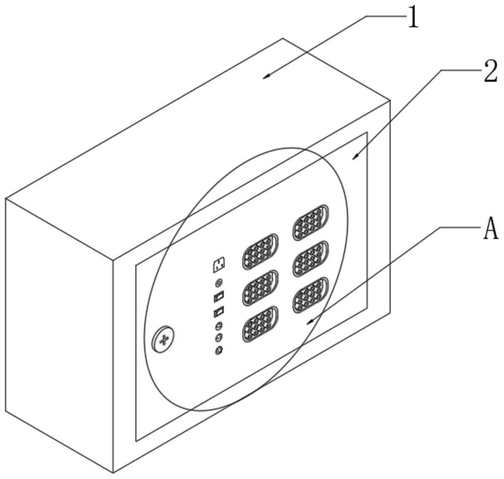
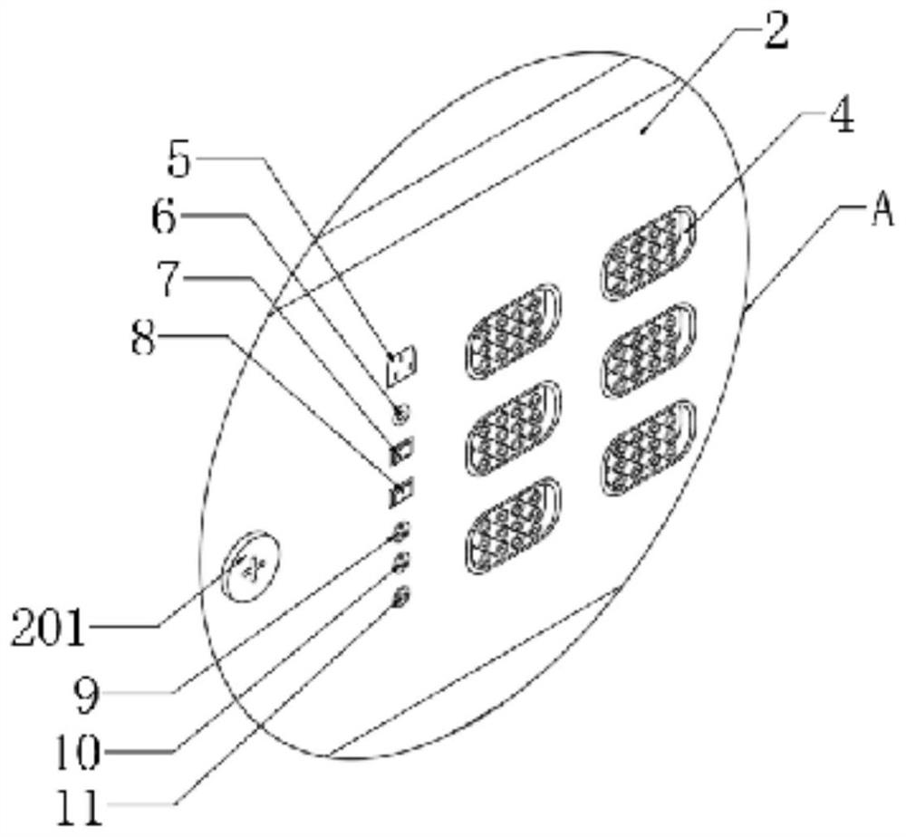
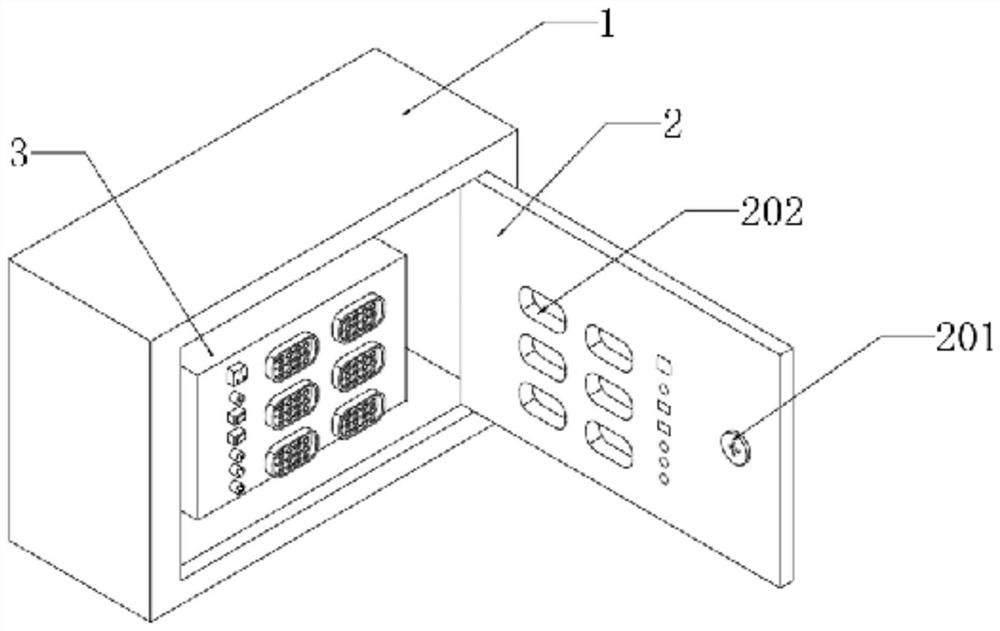
Universal circuit breaker test conversion terminal box
A transfer terminal and circuit breaker technology, which is used in circuit breaker testing, instruments, and components of electrical measuring instruments, etc., can solve problems such as difficulty in releasing, needing to unlock the lock during work, slipping of aviation plugs, and potential safety hazards. , to avoid the risk of electric shock and mechanical injury, improve the reliability of power supply, and reduce power outage time.
- Summary
- Abstract
- Description
- Claims
- Application Information
AI Technical Summary
Problems solved by technology
Method used
Image
Examples
Embodiment 1
[0027] Embodiment one: design and select the signal input terminal, as table 1, is the signal channel test result table of test line-three-core aviation plug base 9;
[0028] Use a signal generator and an oscilloscope to test the signal channel. The specific test method is: connect the modified test line to the three-core aviation plug base 9, and connect the output terminal of the signal generator to the instrument end of the test line. Connect the pins of the base 9 of the core aviation plug to the oscilloscope, use the signal generator to send out square wave pulses, and use the oscilloscope to observe whether the received signal is distorted or attenuated; for each signal channel, send 20 square wave pulses successively for testing; The test results of one of the signal channels are shown in Table 1.
[0029]
[0030] Table I
Embodiment 2
[0031] Embodiment two: design and select the signal output terminal, such as Table 2, which is a three-core aviation plug base 9-secondary aviation socket 4 signal channel test result table;
[0032] Use a signal generator and an oscilloscope to test the signal channel. The specific test method is: connect the output terminal of the signal generator to the 9-pin of the three-core aviation plug base, connect the 4-pin of the secondary aviation socket to the oscilloscope, and use the signal generator Send out square wave pulses, use an oscilloscope to observe whether the received signal is distorted or attenuated; for each signal channel, send 20 square wave pulses successively for testing, and the test results of one of the signal channels are shown in Table 2.
[0033]
[0034] Table II
PUM
 Abstract
Description
Claims
Application Information
 - R&D
- Intellectual Property
- Life Sciences
- Materials
- Tech Scout
- Unparalleled Data Quality
- Higher Quality Content
- 60% Fewer Hallucinations
Browse by: Latest US Patents, China's latest patents, Technical Efficacy Thesaurus, Application Domain, Technology Topic, Popular Technical Reports.
© 2025 PatSnap. All rights reserved.Legal|Privacy policy|Modern Slavery Act Transparency Statement|Sitemap|About US| Contact US: help@patsnap.com


