Time domain direct wave suppression method for short-wave over-the-horizon radar with transmitting and receiving split

A technology of over-the-horizon radar, transceiver separation, applied in measurement devices, radio wave measurement systems, radio wave reflection/re-radiation and other directions, can solve problems such as poor direct wave suppression effect, improve the suppression effect, avoid the amplitude Noise and Phase Noise, Effects of Improved Suppression

Pending Publication Date: 2022-03-08
HARBIN INST OF TECH
View PDF0 Cites 0 Cited by
  • Summary
  • Abstract
  • Description
  • Claims
  • Application Information

AI Technical Summary

Problems solved by technology

[0005] The purpose of the present invention is to solve the problem that the existing method has poor direct wave suppression effect, and propose a time-domain direct wave suppression method for short-wave over-the-horizon radar with separate transceivers

Method used


Image

  • Time domain direct wave suppression method for short-wave over-the-horizon radar with transmitting and receiving split
  • Time domain direct wave suppression method for short-wave over-the-horizon radar with transmitting and receiving split
  • Time domain direct wave suppression method for short-wave over-the-horizon radar with transmitting and receiving split

Examples


specific Embodiment approach 1

[0030] Specific implementation mode 1: In this implementation mode, a method for suppressing direct arrival waves in the time domain of a short-wave over-the-horizon radar with separate transceivers, the specific process is as follows:

[0031] Step 1: The radar transmits a signal, and the signal is received by the radar after being reflected by the target, and the received signal is an echo signal;

[0032] Step 2: Reconstruct the ideal reference signal;

[0033] Step 3: using DBF to extract the direct wave from the multi-channel echo signal;

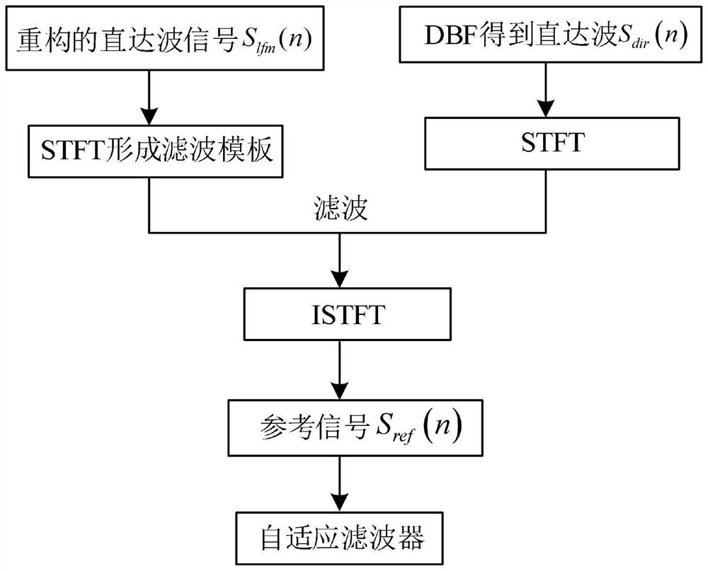
[0034] Step 4: For the reconstructed ideal reference signal S obtained in Step 2 lfm (n) Perform short-time Fourier transform to form a filter template, and then the direct wave signal S obtained in step 3 dir (n) Carry out short-time Fourier transform (Short-time Fourier transform, STFT), use the filter template to filter, obtain the filtering result, and reconstruct the filtering result by short-time Fourier transform to obtain the...

specific Embodiment approach 2

[0041] Embodiment 2: The difference between this embodiment and Embodiment 1 is that the ideal reference signal is reconstructed in Step 2; the specific process is:

[0042] Step 21: generating an ideal LFM signal according to the signal parameters;

[0043] Step 22: Align the distance between the ideal LFM signal and the direct wave component in the echo signal, and perform Doppler alignment on the obtained distance alignment result to obtain the reconstructed ideal reference signal, denoted as S lfm (n).

[0044] Other steps and parameters are the same as those in Embodiment 1.

specific Embodiment approach 3

[0045] Specific embodiment three: the difference between this embodiment and specific embodiment one or two is that in the step two one, an ideal LFM signal is generated according to the signal parameters; the specific process is:

[0046] The complex expression of an ideal LFM signal in one cycle:

[0047] s(t)=Aexp[j(2πft+πkt 2 )], -T / 2≤t≤T / 2

[0048] In the formula, A represents the signal amplitude; f is the signal center frequency; k is the signal frequency modulation slope; T is the pulse repetition period; j is the imaginary number unit, j 2 =-1.

[0049] Other steps and parameters are the same as those in Embodiment 1 or Embodiment 2.


PUM


Abstract

The invention relates to a time domain direct wave suppression method for a transmitting-receiving split short-wave over-the-horizon radar. The invention relates to the time domain direct wave suppression method for the transmitting-receiving split short-wave over-the-horizon radar. The invention aims to solve the problem that the direct wave suppression effect of the existing method is poor. The method comprises the following steps: 1, obtaining an echo signal; 2, reconstructing an ideal reference signal; 3, direct waves are extracted from the multi-channel echo signals through the DBF; 4, performing short-time Fourier transform on the reconstructed ideal reference signal to form a filtering template, performing short-time Fourier transform on the direct wave signal, filtering by adopting the filtering template to obtain a filtering result, and performing short-time Fourier inverse transform reconstruction on the filtering result to obtain a time domain reference signal; and 5, taking the obtained time domain reference signal as a reference signal of an adaptive filter, and carrying out direct wave suppression on the echo signal to obtain the echo signal after direct wave suppression. The method is applied to the field of short-wave beyond-visual-range radar signal processing.

Description

technical field [0001] The invention relates to the field of short-wave over-the-horizon radar signal processing, and can be directly used for direct wave suppression of radars using linear frequency modulated continuous waves (Linear frequency modulated continuous wave, LFM) for target detection under the system of separate sending and receiving. It has reference significance for the direct wave suppression of short-wave over-the-horizon radars that use other signal types for detection. Background technique [0002] The short-wave over-the-horizon radar uses the ionosphere's reflection mechanism of high-frequency electromagnetic waves to achieve over-the-horizon detection of targets. It works in the short-wave band (HF, 3-30MHz) and has a wavelength of 10-100m. It has a large observation range and a long detection distance. It has the advantages of long distance, strong anti-interference ability, strong anti-stealth, low cost, etc., and has important application value in th...

Claims


Application Information

Patent Timeline
Patent Type & Authority Applications(China)
IPC IPC(8): G01S7/36G01S13/32
CPCG01S7/36G01S13/32
Inventor 耿钧郭依佳李浩然
Owner HARBIN INST OF TECH
Why Eureka
Try Eureka