Power-off monitoring device and method and external protection equipment
A technology of protective equipment and monitoring devices, applied in the field of external protective equipment, can solve the problems of destroying the protected equipment, and the protected equipment is out of safety supervision, etc.
- Summary
- Abstract
- Description
- Claims
- Application Information
AI Technical Summary
Problems solved by technology
Method used
Image
Examples
Embodiment approach
[0045] As another implementation manner, the power-taking port dedicated to the power-off monitoring device is provided by a USB interface of the protected device. Conventional 5V USB interface can realize power supply. The power-off monitoring device is connected to the USB port of the protected device through the power-taking line, and the USB connection line between the protected device and the power-off monitoring device can be realized by monitoring the voltage of the USB connection in addition to physical reinforcement means. Plugging and unplugging monitoring of connecting wires.
[0046] The power-taking and connecting module may include an automatic switch, for example implemented by a relay, which is connected to the power supply line of the external protective device; when the power supply line of the external protective device is working normally, the automatic switch makes the The power-taking line is disconnected, and when the power supply line of the external p...
no. 1 example
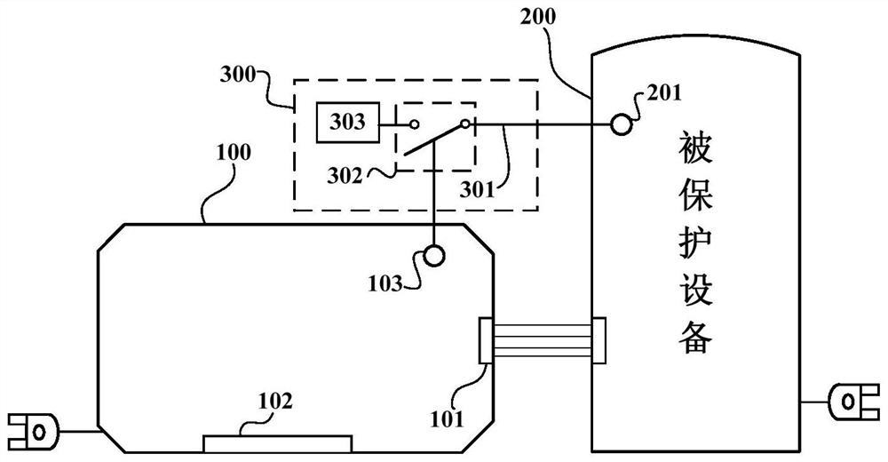
[0065] figure 1 It is a structural schematic diagram of the first embodiment of the power failure monitoring device applied to external terminal protection equipment of the present invention. Such as figure 1 As shown, the power-off monitoring device 300 is used for monitoring and warning the abnormal power-off of the external protective equipment 100 . The external protection device 100 is connected to the corresponding interface of the protected device 200 through the internal interface 102 , and connected to one or more external devices through the external interface 101 . The internal interface 102 and the external interface 101 may be one or multiple. In the figure, only blocks are used to schematically represent the connection relationship of the interfaces. The actual type and quantity of the interfaces may vary according to specific application scenarios.
[0066] Such as figure 1 As shown, the external protective device 100 and the protected device 200 are respecti...
no. 2 example
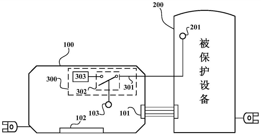
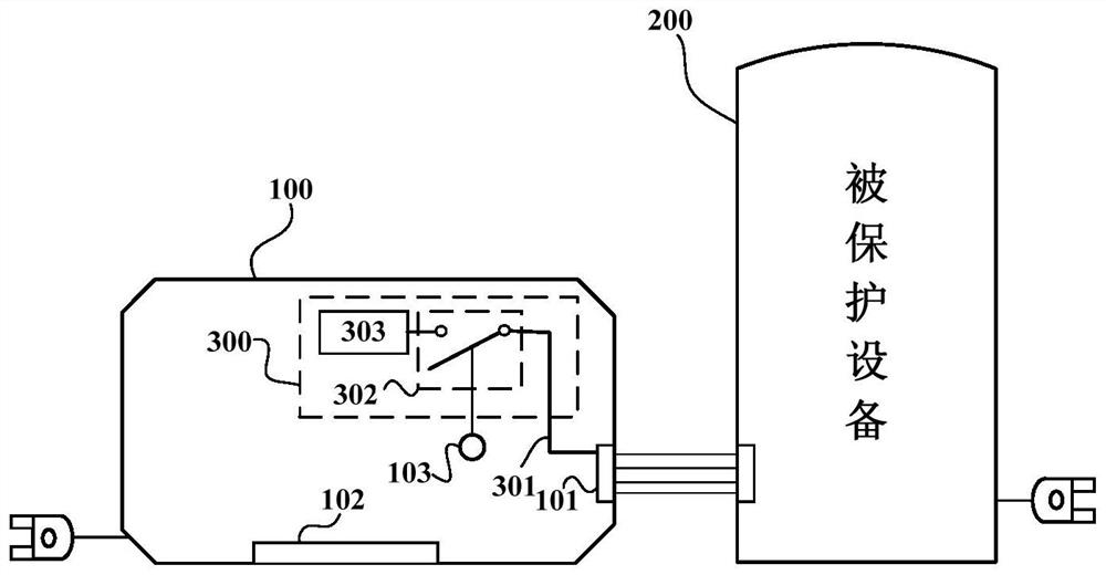
[0077] figure 2 It is a structural schematic diagram of the second embodiment of the power failure monitoring device applied to external terminal protection equipment of the present invention. Such as figure 2 As shown, different from the first embodiment, the automatic switches of the warning module 303 and the power-taking and switching-on module 302 of the second embodiment are located inside the external protective equipment 100, or in other words, the second part of the power failure monitoring device 300 The embodiment is installed inside the casing of the external protective device 100 . The power-taking line 301 is connected to the dedicated power-taking port 201 of the protected device 200 through an interface of the external protective device 100 , and similarly, the dedicated power-taking port 201 is connected to the power supply line in the protected device 200 . The interface of the external protective device 100 used by the power-taking line 301 may be a dedi...
PUM
 Abstract
Description
Claims
Application Information
 - R&D
- Intellectual Property
- Life Sciences
- Materials
- Tech Scout
- Unparalleled Data Quality
- Higher Quality Content
- 60% Fewer Hallucinations
Browse by: Latest US Patents, China's latest patents, Technical Efficacy Thesaurus, Application Domain, Technology Topic, Popular Technical Reports.
© 2025 PatSnap. All rights reserved.Legal|Privacy policy|Modern Slavery Act Transparency Statement|Sitemap|About US| Contact US: help@patsnap.com


