
Protection circuit capable of preventing wrong voltage access
A technology for protecting circuits and voltage input terminals, applied in emergency protection circuit devices, electrical components, etc., can solve problems such as damage to low-voltage controllers and low-voltage electrical appliances, inability to protect high-voltage AC voltage, and fire, etc. Comprehensive and comprehensive cost-effective effect
- Summary
- Abstract
- Description
- Claims
- Application Information
AI Technical Summary
Problems solved by technology
Method used
Image

Examples
Embodiment Construction
[0013] The present invention will be described in detail below in conjunction with the accompanying drawings and specific embodiments.
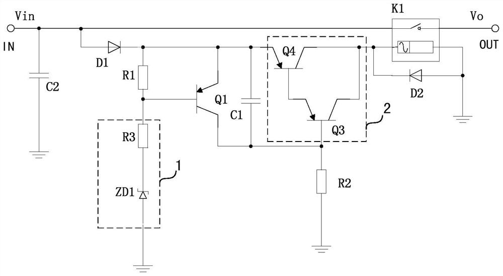
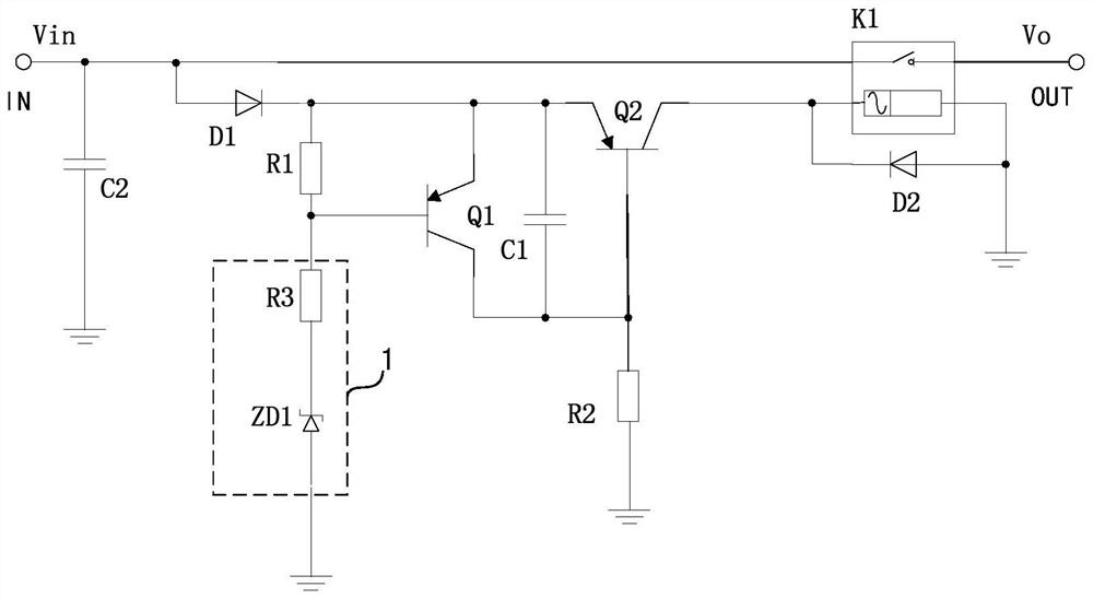
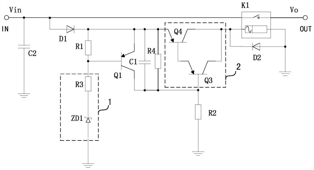
[0014] figure 1 A circuit diagram of a protection circuit capable of preventing wrong voltage access according to the first embodiment of the present invention is shown. see figure 1 . A protection circuit capable of preventing wrong voltage access according to the first embodiment of the present invention includes a voltage input terminal IN, a voltage output terminal OUT, a first unidirectional conduction element D1, a transistor control circuit 1, a first transistor Q1, The first capacitor C1, the Darlington tube 2, the first resistor R1, the second resistor R2 and the relay K1.
[0015] The normally open contact of the relay K1 is connected in series between the voltage input terminal IN and the voltage output terminal OUT. Wherein, one end of the normally open contact of the relay K1 is connected to the voltage input terminal IN, and...
PUM
 Abstract
Description
Claims
Application Information