Microimaging focus locking system and method and microscope

A micro-imaging and focus-locking technology, applied in the field of microscopes, can solve the problems of high optical path coaxiality, poor coaxiality, and increased difficulty in system installation and adjustment, so as to simplify the mechanism, reduce the difficulty of processing and adjustment, The effect of a small number of components

Pending Publication Date: 2022-05-24
广东粤港澳大湾区黄埔材料研究院
View PDF0 Cites 0 Cited by
  • Summary
  • Abstract
  • Description
  • Claims
  • Application Information

AI Technical Summary

Problems solved by technology

However, in the existing focus locking system, the detection signal and the feedback signal must be reflected by the dichroic mirror and magnified by the objective lens, so this design requires high coaxiality of the optical path, and poor coaxiality will lead to detection The feedback signal cannot be collected by the controller, which increases the difficulty of system installation and adjustment

Method used


Image

  • Microimaging focus locking system and method and microscope
  • Microimaging focus locking system and method and microscope
  • Microimaging focus locking system and method and microscope

Examples


Embodiment 1

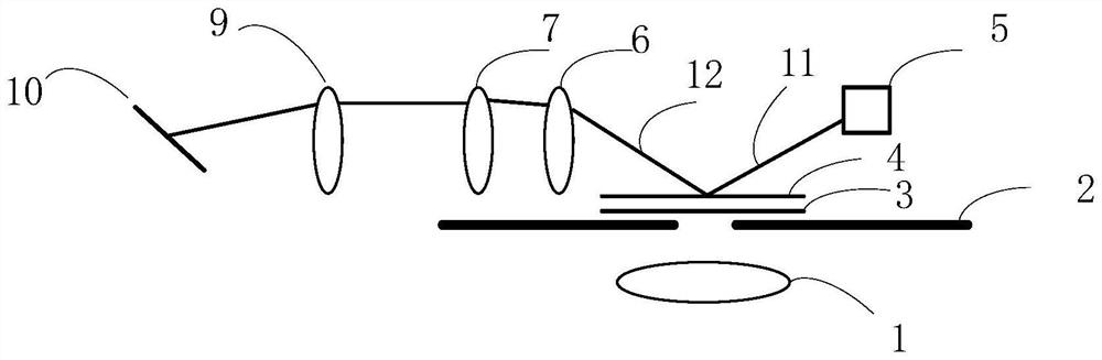
[0024] like figure 1 As shown, the present invention discloses a microscopic imaging focus locking system, comprising a light source 5, a first lens 6, a second lens 7, a third lens 9, a detector 10 and an objective lens displacement controller; the light source 5 is used for To generate incident light, the first lens 6, the second lens 7 and the third lens 9 are sequentially arranged on the propagation path of the reflected light beam 12, and the reflected light beam 12 is formed by the incident light beam 11 reflected by the upper surface 4 of the glass slide; The first lens 6 and the second lens 7 form a beam expander group, the beam expander group is used to amplify the offset, and the third lens 9 is used to converge the reflected light beam 12 to a beam set at a first angle. Detector 10, the detector 10 is used to compare the first position of the first spot formed by the reflected light beam 12 with the initial position of the pre-stored initial spot, and send the first...

Embodiment 2

[0041] The invention also discloses a microscopic imaging focus locking method, comprising:

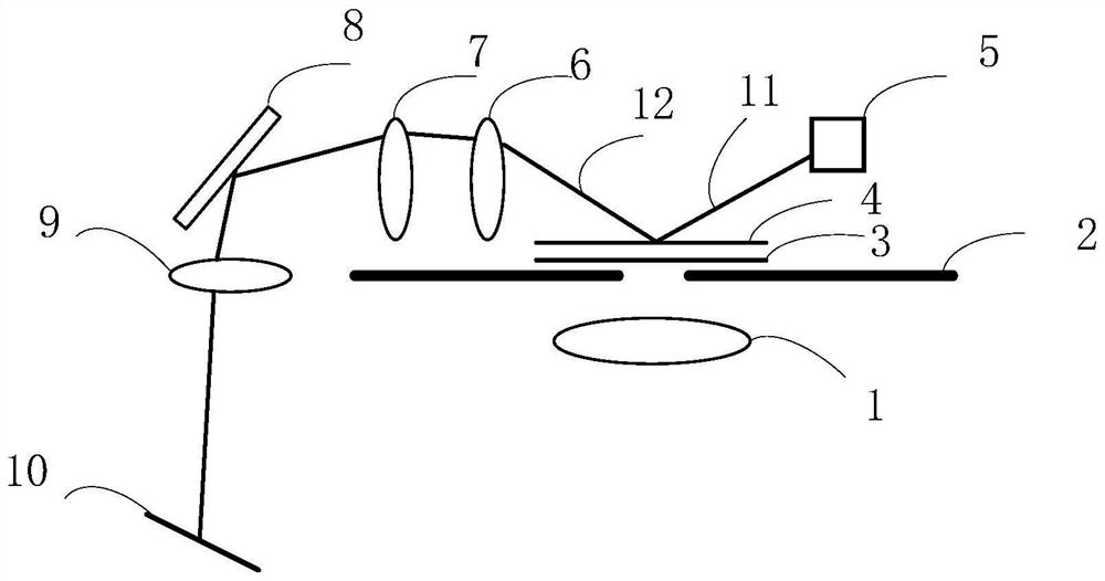
[0042] Correct the focus-locking system to obtain the initial position of the initial spot. The focus-locking system includes: a light source 5, a first lens 6, a second lens 7, a third lens 9, a detector 10 and an objective lens displacement controller; the light source The incident light emitted by 5 is reflected by the upper surface 4 of the glass slide to form a reflected light. The reflected light passes through the first lens 6, the second lens 7 and the third lens 9 in sequence and then converges on the detector 10 to form an initial spot and record the initial spot of the initial spot. position; the first lens 6 and the second lens 7 form a beam expander group, the beam expander group is used to amplify the offset, and the third lens 9 is used to converge the reflected beam 12 to a first angle set detector 10;

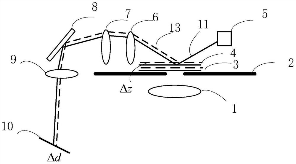
[0043] When the slide is displaced in the vertical direction, th...

Embodiment 3

[0050] The present invention also discloses a microscope, which applies the focus locking system described in Embodiment 1.

[0051] In this embodiment, the microscope may be an inverted fluorescence microscope. The focus locking system of the present invention can be matched with various types of microscopes, and is not limited to a certain microscope.

[0052] To sum up, the embodiments of the present invention provide a microscopic imaging focus locking system, method and microscope, the beneficial effects are: the focus locking system of the present invention in which the incident light does not enter the objective lens 1, when the focus is locked, the microscopic imaging system is affected. Dependence and influence can be ignored; the focus locking system has fewer components and a simplified mechanism, which reduces the difficulty of processing and assembling, and is a modular system that is easier to implement; the focus locking system of the present invention is compat...


PUM


Abstract

The invention belongs to the technical field of microscopes, and discloses a microscopic imaging focus locking system and method, and a microscope, and the system comprises a light source, a first lens, a second lens, a third lens, a detector, and an objective lens displacement controller. The light source irradiates the glass slide to form reflected light which sequentially passes through the first lens, the second lens and the third lens, the first lens and the second lens are used for amplifying offset, and the third lens is used for converging reflected light beams to the detector arranged at a first angle. The detector is used for comparing the first position of a first light spot formed by the reflected light beam with the initial position of a pre-stored initial light spot, and sending a first control signal to the objective lens displacement controller according to the first position and the second position. The device has the beneficial effects that the dependence and influence on a microscopic imaging system can be neglected when the focus locking is carried out by a focus locking system in which incident light enters without an objective lens; the device number of the focus locking system is small, the mechanism is simplified, the processing, assembling and adjusting difficulty is reduced, and the modular system is easier to realize.

Description

technical field [0001] The invention relates to the technical field of microscopes, in particular to a microscopic imaging focus-locking system, method and microscope. Background technique [0002] Due to the vibration in the environment and the influence of temperature, when doing microscopic imaging, the sample will inevitably be affected by various factors in the environment, and the axial deviation will occur, which will cause the sample surface to be out of focus. , the greater the impact of focal plane deviation. Therefore, it is necessary to add a focus locking system to the microscope. [0003] The existing automatic focus locking technology generally uses the position of the light spot formed on the photodetector by the reflected light on the glass slide to calculate the compensation distance of the objective lens. However, in the existing focus-locking system, the detection signal and the feedback signal are both reflected by the dichroic mirror and amplified by ...

Claims


Application Information

Patent Timeline
IPC IPC(8): G02B21/24
CPCG02B21/241G02B21/245
Inventor 孙佳音杨乐宝王宏达
Owner 广东粤港澳大湾区黄埔材料研究院
Why Eureka
Try Eureka