Laser cutting machine for part machining

A technology for laser cutting machine and parts processing, applied in laser welding equipment, metal processing equipment, manufacturing tools, etc., can solve the problems of low processing efficiency of parts, high installation cost, complex structure, etc., and achieve continuous transportation and improve processing efficiency. Effect

Active Publication Date: 2022-03-11
江苏觅科激光设备有限公司
View PDF6 Cites 1 Cited by
  • Summary
  • Abstract
  • Description
  • Claims
  • Application Information

AI Technical Summary

Problems solved by technology

[0003] At present, when the laser cutting machine is cutting and processing the parts, it needs to use the telescopic movement of the hydraulic cylinder or the forward and reverse rotation of the motor screw to continuously transport multiple groups of parts to the direction of the laser cutting mechanism. The supply method of this kind of parts involves The structure obtained is relatively complex, and the continuous delivery of parts needs to be controlled by the controller and related programs to control the reciprocating motion of the hydraulic cylinder and the forward and reverse rotation of the motor screw, resulting in low processing efficiency of the parts and high cost of the devices involved.

Method used


Image

  • Laser cutting machine for part machining
  • Laser cutting machine for part machining
  • Laser cutting machine for part machining

Examples


Embodiment Construction

[0029] The technical solution of this patent will be further described in detail below in conjunction with specific embodiments.

[0030] Embodiments of the present patent are described in detail below, examples of which are shown in the drawings, wherein the same or similar reference numerals designate the same or similar elements or elements having the same or similar functions throughout. The embodiments described below by referring to the figures are exemplary and are only used for explaining the patent, and should not be construed as limiting the patent.

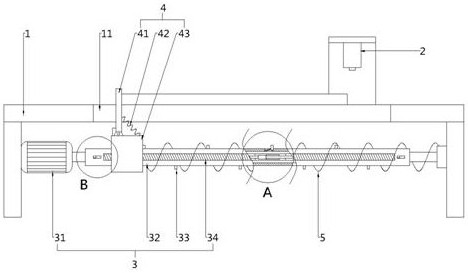
[0031] see figure 1 , this embodiment provides a laser cutting machine for part processing, including a processing table 1, a laser cutting mechanism 2, a driving mechanism 3, a pushing mechanism 4 and a first elastic member 5, and the laser cutting mechanism 2 is arranged on the One side of the processing table 1 is used for cutting parts, the pushing mechanism 4 is movably installed on one side of the processing tabl...


PUM


Abstract

The invention provides a laser cutting machine for part machining, and belongs to the technical field of laser cutting machines, the laser cutting machine comprises a machining table, a laser cutting mechanism, a driving mechanism, a pushing mechanism and a first elastic piece, the laser cutting mechanism is arranged on one side of the machining table and used for cutting parts, and the driving mechanism is arranged on the other side of the machining table; the material pushing mechanism is movably installed on one side of the machining table, the driving mechanism and the first elastic piece are both connected with the material pushing mechanism, and the driving mechanism is used for driving the material pushing mechanism to move in the direction away from the laser cutting mechanism. And the pushing mechanism is driven to cross the part and abut against the side, away from the laser cutting mechanism, of the part. Compared with the prior art, a complex control system does not need to be used, continuous conveying of a plurality of parts and intermittent conveying of a single part can be achieved while the rotating direction of the motor is not changed, and therefore the machining efficiency of the parts is improved.

Description

technical field [0001] The invention belongs to the technical field of laser cutting machines, in particular to a laser cutting machine for parts processing. Background technique [0002] The laser cutting machine focuses the laser emitted from the laser into a high-power-density laser beam through the optical path system. The laser beam irradiates the surface of the workpiece to make the workpiece reach the melting point or boiling point. At the same time, the high-pressure gas coaxial with the beam will melt or Vaporized metal blows away. [0003] At present, when the laser cutting machine is cutting and processing the parts, it needs to use the telescopic movement of the hydraulic cylinder or the forward and reverse rotation of the motor screw to continuously transport multiple groups of parts to the direction of the laser cutting mechanism. The supply method of this kind of parts involves The structure obtained is relatively complex, and the continuous delivery of parts...

Claims


Application Information

Patent Timeline
Patent Type & Authority Applications(China)
IPC IPC(8): B23K26/38B23K26/70
CPCB23K26/38B23K26/702
Inventor 穆浩
Owner 江苏觅科激光设备有限公司
Why Eureka
Try Eureka