
INS (Inertial Navigation System) film-coated cavity for automotive trim

A technology for automobile interior decoration and lamination, applied in the field of automobile interior decoration assembly, can solve the problems of abnormal assembly noise, uneven gap, surface difference, etc., and achieve the effect of good practicability, reduction of processes, and reduction of welding processes

Pending Publication Date: 2022-03-11
CHENGDU AEROSPACE MOLD & PLASTIC CO LTD
View PDF0 Cites 1 Cited by
  • Summary
  • Abstract
  • Description
  • Claims
  • Application Information

AI Technical Summary

Problems solved by technology

[0004] The invention provides an INS film-coated cavity for automotive interiors, which aims to integrally form automotive interior accessories, solve the problems of abnormal noise, surface difference, and uneven gaps in the assembly of automotive interiors, and reduce the welding process of parts. Enhances the sophistication of the interior

Method used


Image

  • INS (Inertial Navigation System) film-coated cavity for automotive trim
  • INS (Inertial Navigation System) film-coated cavity for automotive trim

Examples


Embodiment 1

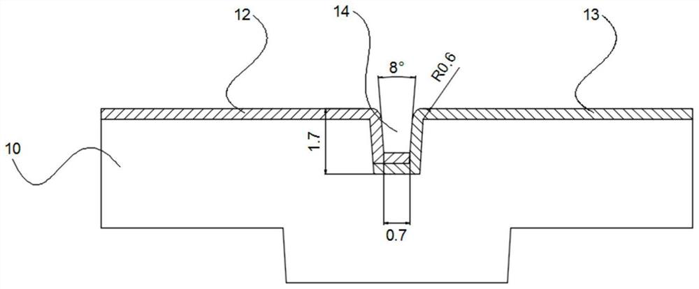
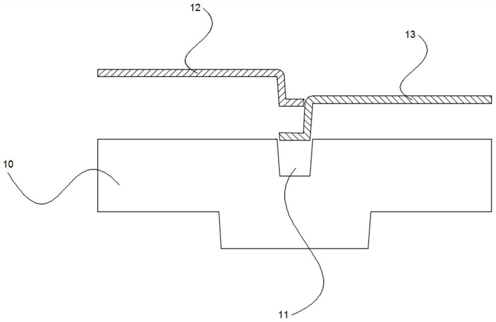
[0031] A INS coating cavity for automotive interior, including processing panel 10, first INS diaphragm 12, and second INS diaphragm 13, and a groove 11 is provided with a groove 11, the groove. 11 The longitudinal section of the longitudinal section is inverted, the first INS diaphragm 12 and the second INS diaphragm 13 located at the top of the machining panel 10, and one end of the first INS diaphragm 12 and the second INS diaphragm 13. A process slot 14 is formed between the groove 11 and bonded to the groove 11, and the first INS diaphragm 12 and the second INS diaphragm 13 are formed, and the first INS diaphragm in the groove 11 is formed. 12 The end is covered with the top of the end of the second INS diaphragm 13.

[0032] When the first INS diaphragm 12 and the second INS diaphragm 13 are used, the first INS diaphragm 12 and the second INS diaphragm 13 are provided on the machining panel 10 and are sent to the injection mold, and the plastic bag. The top portion of the fi...

Embodiment 2

[0034] This embodiment is optimized on the basis of Example 1, such as Figure 1 - Figure 2 As shown, the groove 11 is bent by a machining panel 10.

[0035] The groove 11 of the processing panel 10 is composed of stamping, avoiding the use of tool slots and reduces the process.

[0036] The other portions of the present embodiment are the same as in Example 1, so it will not be described again.

Embodiment 3

[0038] This embodiment is optimized on the basis of Example 1 or 2, such as figure 1 As shown, the inclination angle of the process tank 14 is a, height h, a width D, and the inclined angle A is 6 ° -8 °, the height H ranges from 1.7 mm to 2.5 mm, The width D ranges from 0.7 mm to 0.9 mm;

[0039] Among them, the optimization is that the inclination angle A is 6 °, the height H is 1.7 mm, and the width D is 0.7 mm. The inclination angle A ranges from 6 ° -8 °, the height H ranges from 1.7 mm to 2.5 mm, and the range D is 0.7mm to 0.9mm, and the above parameters are set, which makes the appearance of the injection molded product meet the requirements, and easy The product is removed from the first INS diaphragm 12 and the second INS diaphragm 13 without sticking.

[0040] The other portions of the present embodiment are the same as those of the above-described Embodiment 1 or 2, so it will not be described again.


PUM

PropertyMeasurementUnit
angleaaaaaaaaaa
heightaaaaaaaaaa
widthaaaaaaaaaa

Abstract

The invention discloses an INS (Inertial Navigation System) film-coated cavity for automotive trim, which comprises a processing panel, a first INS film and a second INS film, a groove is formed in the top of the processing panel, the longitudinal section of the groove is an inverted isosceles trapezoid, the first INS film and the second INS film are respectively positioned at the top of the processing panel, and the first INS film and the second INS film are respectively positioned at the bottom of the processing panel. One end of the first INS diaphragm and one end of the second INS diaphragm respectively extend into the groove and are attached to the groove, a process groove is formed between the first INS diaphragm and the second INS diaphragm, and the end of the first INS diaphragm in the groove covers the top of the end of the second INS diaphragm; two interior trim parts with different lines can be integrally formed, the problems that in the prior art, due to threaded connection of the two interior trim parts with the different lines, abnormal sound, surface difference, uneven gaps and the like of automobile interiors are caused are solved, meanwhile, the welding procedure of parts is reduced, and the delicate feeling of the interiors is improved.

Description

Technical field [0001] The present invention belongs to the technical field of automotive interior assembly, and more particularly to an INS coating cavity for automotive interiors. Background technique [0002] Traditional car decorative board If you need a plurality of decorative effects on a product, you can only make the disassembly, and it is necessary to make more tooling and human costs; and because the length of the trim strip will directly affect its shape. Whether it will deformed, resulting in the design process, the designer will be very concerned about whether the structure of its own design can be produced, often need to break down into a plurality of components, so that the design and installation of the mold will increase the cost, appearance It is also better than the structure of a multi-embossed articulating film. At the same time, the products obtained may have an interior assembly, the facial difference, and the gap is unequal. [0003] Therefore, in order to...

Claims


Application Information

Patent Timeline
Patent Type & Authority Applications(China)
IPC IPC(8): B29C45/26B29L31/30
CPCB29C45/2602B29C45/263B29L2031/3005
Inventor 刘东邓毅学张辉李新
Owner CHENGDU AEROSPACE MOLD & PLASTIC CO LTD
Learn More