Rotary position sensor

A technology of rotating position and sensor, which is applied in the field of position sensing, can solve problems such as sensor malfunction, sensor failure, loss of support, etc., achieve good insulation and adhesion, eliminate the influence of temperature, and achieve long-term use effects

Pending Publication Date: 2022-03-11
LESHAN NORMAL UNIV
View PDF0 Cites 0 Cited by
  • Summary
  • Abstract
  • Description
  • Claims
  • Application Information

AI Technical Summary

Problems solved by technology

Since the rotary position sensor must give an appropriate electrical signal based on the measured position, the measurement of the rotary position sensor needs to be sufficiently accurate, so the position sensor needs to be durable enough for the environment in which it is placed, such as for the position of a motor vehicle valve Sensors, in the process of operation of the car, experience almost continuous motion, whether it is large mechanical vibration or thermal extremes, thermal gradient conditions, the sensor should maintain precision and accuracy within its design life; however, the current The measurement accuracy of many rotary position sensors varies with the specific use environment
[0003] Moreover, the structure of the existing rotary position sensor is complicated, and the interior is assembled by multiple electrical and electrical components, and a large amount of insulating materials are used for support and electrical isolation
In order to meet different electrical and mechanical requirements, these sensors inevitably use a variety of different insulating materials, and most of these insulating materials become brittle in low temperature environments, reduce toughness, and cause cracks under vibration and mechanical shock, making insulation failure , and lose the supporting function, which causes the sensor to fail; some sensors use permanent magnetic materials inside, and most of the permanent magnetic materials weaken at low temperatures, resulting in the failure of this type of rotary position sensor

Method used


Image

  • Rotary position sensor
  • Rotary position sensor
  • Rotary position sensor

Examples


Embodiment

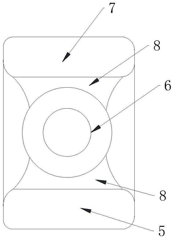
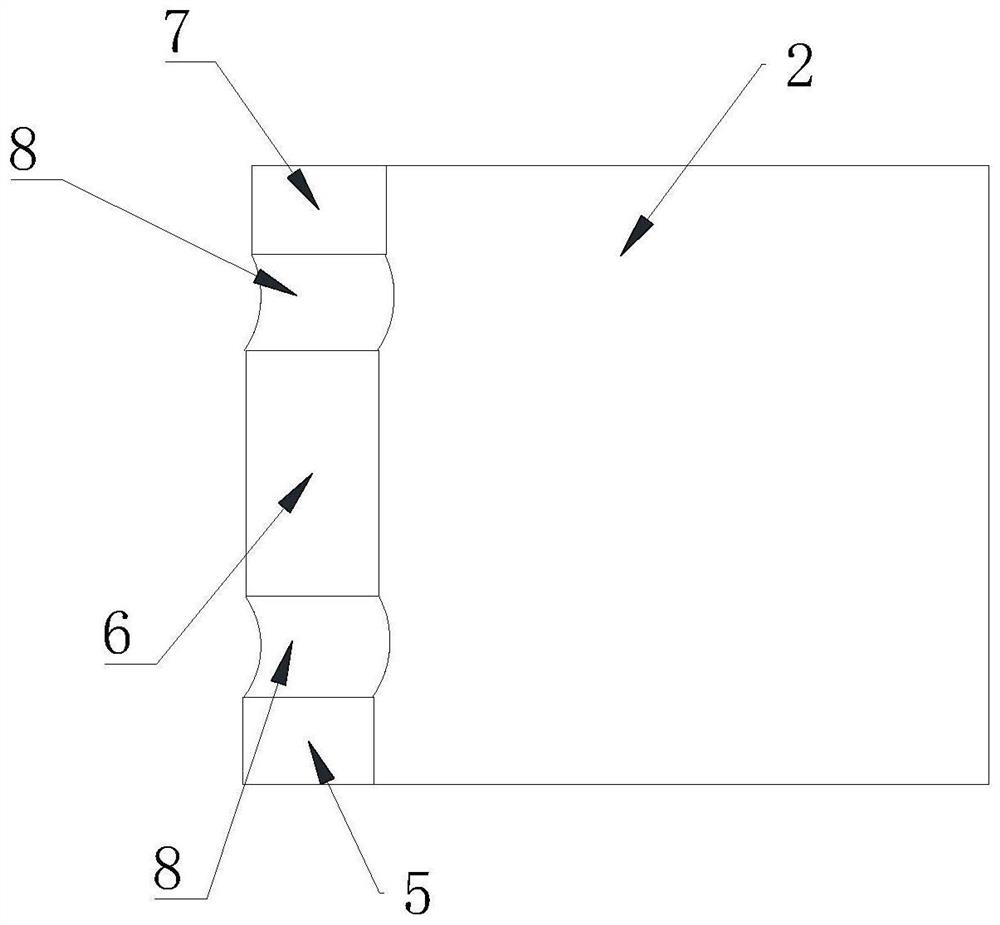
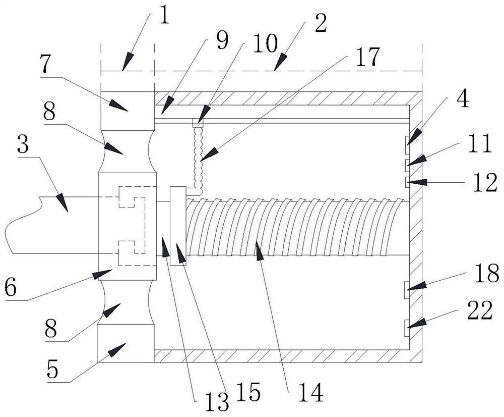
[0038] Example: Rotary position sensor such as Figure 1 to Figure 7 As shown, it includes a front housing 1, a rear housing 2 affixed to the front housing 1, and a controller 4 (the controller 4 adopts a PLC single-chip microcomputer); the front housing 1 includes a base block 5, a cylindrical portion 6, a support block 7 and 2 arc-shaped plates 8 symmetrically arranged and fixed to the cylindrical part 6; The top end is affixed; the use of the arc plate 8 helps to connect the cylindrical part 6 with the support block 7 and the base block 5 respectively; the use of the cylindrical part 6 helps to connect the rotating body 3, the linkage body 13 and the screw rod 14 , so that the rotational motion can be transmitted to the screw 14 and the nut 15 , so that the rotational position can be determined through the relative movement between the screw 14 and the nut 15 .

[0039]The end surface of the support block 7 close to the rear housing 2 is fixedly connected with a convex fix...


PUM


Abstract

The invention discloses a rotary position sensor, which belongs to the technical field of position sensing, and is characterized by comprising a front shell, a rear shell and a controller, the front shell comprises a base block, a cylinder part, a supporting block and two arc-shaped plates; the end face of the side, close to the rear shell, of the supporting block is fixedly connected with a convex fixed ruler. The bottom surface of the convex fixed ruler is connected with a concave sliding ruler in a sliding manner; a rotating body and a linkage body are embedded in the inner wall of the cylinder part; one end of the linkage body is joggled with the rotating body, the other end of the linkage body is fixedly connected with a screw rod, the outer wall of the screw rod is sleeved with a nut, and the outer wall of the screw rod is meshed with the inner wall of the nut; a round groove is formed in the end face of the side, away from the linkage body, of the nut, an L-shaped rod is movably connected into the round groove, and the top end of the L-shaped rod is fixedly connected with the concave sliding ruler. The device is mainly used for multi-gear rotary input or a multi-gear rotary switch, can freely and continuously rotate, is simple in structure, reliable in operation and accurate in measurement, and can effectively eliminate temperature influence so as to realize long-term use.

Description

technical field [0001] The invention relates to the technical field of position sensing, in particular to a rotary position sensor. Background technique [0002] Rotary position sensors are used to electronically monitor the position or movement of mechanical parts. Rotary position sensors generate an electrical signal that varies with the position of the part and are used in a variety of products. Since the rotary position sensor must give an appropriate electrical signal based on the measured position, the measurement of the rotary position sensor needs to be sufficiently accurate, so the position sensor needs to be durable enough for the environment in which it is placed, such as for the position of a motor vehicle valve Sensors, in the process of operation of the car, experience almost continuous motion, whether it is large mechanical vibration or thermal extremes, thermal gradient conditions, the sensor should maintain precision and accuracy within its design life; howe...

Claims


Application Information

Patent Timeline
Patent Type & Authority Applications(China)
IPC IPC(8): G01B7/00
CPCG01B7/003
Inventor 常峰蒋强祝加雄卢林菊
Owner LESHAN NORMAL UNIV
Why Eureka
Try Eureka